|
The ELBE accelerator is operated with a time structure of
the electron beam which is either cw or pulsed mode with
a macropulse length down to 100 ms. Because of this time
structure it is straightforward to use electronics
operating in the frequency domain for the beam position
monitors (BPM). The stripline
BPM has a large bandwidth, at least 6 GHz, which we can
see by means of a Network analyzer. The idea is to
take a part of the BPM RF signal and to send it through
electronics which will give a rms of the RF signal;
in other words the electronics will convert the RF signal
to DC with an amplitude proportional to the power of the RF
signal. Microchips with 2.5 GHz bandwidth which can treat RF signals
in this way are now available. There are two
possible schemes of the BPM electronics under development.
The first one is based on the logarithmic amplifier AD8313,
the other one on the rms-responding true power detector AD8361.
The features of the chips are shown in Fig.1.
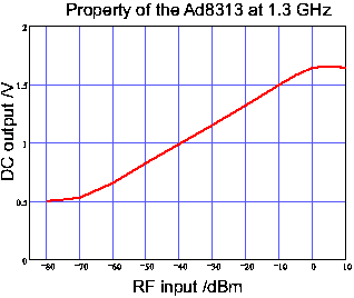
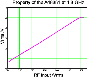
Fig. 1 Characteristics of the chips which are used for the BPM electronics. The block-diagrams of the proposed electronics are given in Fig. 2.
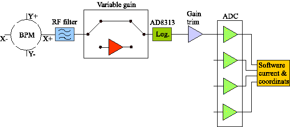
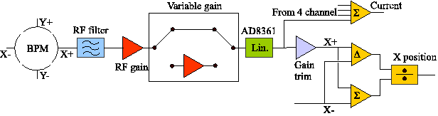
Fig. 2 Proposed schemes of the BPM electronics, based on the logarithmic amplifier AD8313 (top) and on rms-responding true power detector AD8361(bottom). The electronics based on the AD8361 allows to calculate the electron beam position in an analog device and thus it can be more useful in time critical measurements. The scheme based on the logarithmic amplifier does not give such a possibility. In this case position and current will be calculated by software which results in a longer evaluation time. Such software for the BPM system was done in LabView.
|