|
The U27 undulator consists of two 0.98 m long separate sub-systems which have
individual mechanical drives for gap adjustment. Thus for variable gaps the radiation wavelength is changed and consequently the phasing between the two undulator
systems has to be changed as well. This has to be done by properly choosing the
electron flight path d between the two sections.
The optical phase in an undulator has been analyzed in detail by Walker[1]. It can
be expressed by

|
(1)
|
Here z is the coordinate along the beam axis, lR is
the radiation wavelength, g is the electron kinetic energy in units
of its rest mass and Q is the electrons deflection angle.
The terms in the bracket have the following descriptive meaning:
the first gives the contribution to the phase,
if the electron travels just a distance z in free space, the second term represents
the additional contribution due to the magnetic field.
The function Q(z) can be derived from By(z) by
|
Q(z) = |
e
bgm0c
|
|
ó
õ
|
z
|
dz¢By(z¢) . |
| (2) |
Using the eqs. (1) and (2) the phasing of the two undulator sub-systems can be
determined experimentally by measuring By(z) along the axis
of the entire undulator.
The phase on the poles in the second section varies with the
distance d, which depends on the K-value and has to be chosen appropriately.
Moreover, phase matching is obtained periodically after an increase of d by
Dd = lu(1+1/2K2). The deviation of the optical phase angle from its nominal value
obtained for a perfect undulator is denoted by DY(z).
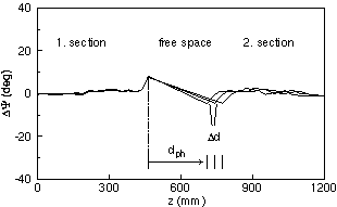
For a gap g = 17 mm measurements for DY(z) are shown in fig. 1.
The K-value for this case was 0.6688.
The nominal phase deviation on the poles is nearly zero,
only at the end poles before and after the interspace the phases deviate from zero.
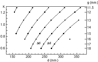
The proper choice of the distances d as functions of the K-value as determined
experimentally is shown in fig. 2. Six different curves have been measured. They
are shifted horizontally by Dd = lu(1+1/2K2(g)). These curves
have to be used to choose phasing distances dph in dependence on the gap g.

|

|
|
Fig. 1
Phase differences DY(z) for a gap g = 17 mm.
The K-value is 0.6688. Three phasing distances dph are shown.
|
Fig. 2
Phasing distances dph (points) between the two sections of U27.
The right axis shows the gap widths g, for which the values dph have been found, the left axis shows the corresponding K-values in a linear scale.
|
1 HASYLAB at Deutsches Elektronen Synchrotron DESY, Hamburg
References
[1] R. P. Walker,
Nucl. Instr. Meth. A 335 (1993) 328
[2] B. Faatz, J. Pflüger, P. Pierini,
Nucl. Instr. Meth. A 375 (1996) 441-444
IKH
05/21/01
© P. Gippner
|


