|
In order to produce at ELBE an intense FEL radiation in the infrared region we shall install the undulator U27 which consists of two sections with a length of 0.98 m each and a short region in between with three adjustable magnetic dipoles.
Each section consists of Nu = 34 magnetic periods with a length of lu = 27.3 mm.
The magnetic structures for both units were test modules for the TTF-Facility at DESY, Hamburg [1,2] and the carriages have been constructed and delivered by DANFYSIK.
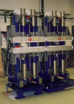
The fig. 1 shows the carriages before the magnets have been mounted.
For optimization of the phase-matching of the two sections the distance between them is adjustable over a wide range by using a stepping motor.
The carriages are designed such that the gap of both sections can be varied independently. For special applications they can also be tapered individually, what should
result in an increase of the extraction efficiency [3,4].
The undulator field was measured and tuned at HASYLAB (DESY) by means of the Hall probe shown in fig. 2.
The probe is mounted on a goniometer with six
degrees of freedom for right adjustment within the magnetic structures.
The poles were tuned with the aim to get a minimum electron displacement at the exit sides of the modules as well as a peak field roughness lower than 0.4 %.
As a result of the measurements the fig. 3 shows the field component By(0,0,z) in the middle plane of both undulator units for a gap of g = 12 mm
and a distance d = 250 mm between the sections (a) and the first integral over the measured field (b).
The trajectory of a reference electron with an energy of E = 20 MeV in the wiggle plane is shown in part (c).
|
|
Fig. 4 shows the magnetic field distribution By(x,0,z5) perpendicular to the electron beam at different gaps , where z5 is the center of the 5th pole.
In order to make the gap variation more convenient we tried to design a ''passive'' undulator. Thereby the elongation of the electrons for a given energy should be nearly
independent of the gap width, whereas the displacement D and the slope of the trajectory at the exit should be as small as possible. Corresponding calculations
have been done with the code RADIA [5] and have already been reported [6]. However
the fringe field turns out to be not absolutely passive against gap widening but causes a weak dependence of D on the gap.
This can be corrected by coils mounted at the entrance sides of both sections and allowing to inject the electrons under a small angle relatively to the z-axis.
Only weak magnetic fields of about 2 mT are necessary to keep the electrons within the optical mode.
Presently the influence of shimming on the fringe field is under investigation.
|
|
Fig. 1 The undulator carriages with girders before mounting the magnetic structures.
|
Fig. 2 The Hall probe mounted on a goniometer for field measurements on the axis of one of the undulator sections.
|
|
|
Fig. 3 The field distribution By(z) in the middle plane of the two undulator systems along the axis z for a gap width of g = 12 mm (see text).
|
Fig. 4 Magnetic field By(x,0,z5) perpendicular to the electron beam at different gaps, where z5 is the position of the 5th pole.
|
1 HASYLAB at Deutsches Elektronen Synchrotron DESY, Hamburg
References
[1] B. Faatz, J. Pflüger and Y.M. Nikitina, Nucl. Instr. Meth. A 375 (1996) 618
[2] Y.M. Nikitina and J. Pflüger, DESY Report TESLA-FEL 96-03
[3] E.L. Saldin, E.A. Schneidmiller and M.V. Yurkov, Phys. Lett. A 185 (1994) 469
[4] D. Jaroszynski et al., Phys. Rev. Lett. 72, 2387 (1994)
[5] P. Elleaume, O. Chubar and J. Chavanne, J. Synchr. Rad. 5 (1998) 481
[6] P. Gippner, W. Seidel and A. Schamlott, Annual Report 1998, FZR-271, p.16
IKH
05/21/01
© P. Gippner
|