|
In 2000 the ENEA undulator U50 was moved from Frascati to Dresden, but up to now we had no the possibility to control the magnetic structure of this equipment for damages originating by shocks during the transport. Corresponding measurements are normally made point by point using a Hall probe. Thereby great care must be taken for a precise mechanics and for the minimization of nonlinearities and calibration errors of the probe. Such measuring technique is not available at our institute. To find new irregularities of the magnetic field By(z) arising from the transport we used the pulsed wire method [1, 2], which seems to be a much simpler technique than the Hall probe is. Parts of the equipment for this method and the software for data acquisition were delivered by ACCEL1. The pulsed wire method enables an in situ measurement of the first and second field integrals I1(z) and I2(z) of the magnetic structure depending on the current pulse form [1,2]. To measure these functions we used a CuBe wire with a diameter of d = 50 mm and length of L = 7500 mm. The tension was produced by a mass of m = 85 g, resulting in a tensile force of P = 0.83 N and a tension of T = 4.24·104 N/cm2. In a first attempt an additional calibration magnet outside the undulator was not applied. The table 1 contains the electric parameters of the measurements.
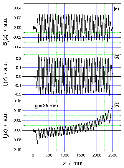
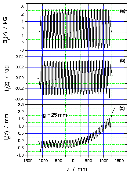
The measured integrals I1(z) and I2(z) in arbitrary units for a gap width of g = 25 mm are shown in fig. 1. The field component By(z) is the derivative of I1(z) and was calculated by the data acquisition program. The fig. 2 allows a comparison with the results obtained at ENEA with the Hall probe technique before the transport to the FZR was carried out. In general one can conclude that no additional field errors arised.

Fig. 1 First field integral I1(z) (part b) and second field integral I2(z) (part c) measured with the pulsed wire method. The derivative By(z) was not measured.

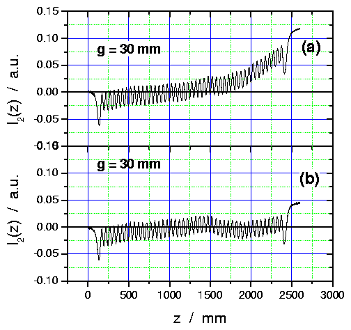
Fig. 2 The field component By(z) in the middle plane (a) measured with the Hall probe technique. The functions I1(z) and I2(z) are obtained by integration of By(z). Finally, fig. 3 shows the second field integrals without and with an application of a homogeneous external field of B = 3.3 G to correct the behaviour of this function. A bending effect can clearly be seen, which will help to guide the electron trajectories through the waist within the optical resonator. More quantitative investigations will be done in near future.

Fig. 3 The integral I2(z) obtained by the pulsed wire method
at a gap of g = 30 mm without (a) and with an additional homogeneous field (b)
of B = 3.3 G in the exit part of the undulator.
1)ACCEL Instruments GmbH, Bergisch-Gladbach
References
|