|
For the FEL beamlines an S-shaped design with achromatic bends
was chosen which performs a compression of the electron
bunch on its way to the FEL undulators.
Both bends of the S use a dipole-quadrupole-dipole layout.
Position and focusing power of the quadrupoles have to
be adjusted to achieve zero position and momentum dispersion.
For the first bend this leads to an asymmetric quadrupole
position, given the asymmetric pole-face angles
of the used dipole magnets.
For each bend a beam matching is possible which results in equal beam radii
at the entrance and exit of the bend.
Given the positions of the dipole magnets
the phase shift in longitudinal phase space is fixed
to R56=93 mm. A preparation of a certain
longitudinal phase-space correlation which leads to
an upright phase-space ellipse at the undulator
is done with a variable-R56 chicane in between
the two accelerator cryomodules.
The straight beamline section between the bends is mainly
determined by mechanical limitations as the beam has to go
through a 2.4 m thick concrete wall in front of which
a beam shutter is placed. Considering this, the quadrupole-doublet
magnetic lens has to be placed inside the concrete wall
immediately behind the shutter in order to limit
the beam magnification. Including two single quadrupoles
at the ends of the straight section an imaging of the matched
beams of the bends onto each other is possible.
The undulator of the mid-infrared FEL consists of two
1 m long segments. Their spacing varies from 245 to 345 mm
determined by the resonance condition between the optical
and the electron beam. Due to the field-free drift space beween the
undulator segments an ideal matching which would
yield a constant-radius envelope is impossible.
Instead, a symmetric matching condition was choosen
which has a beam waist between the undulator segments.
The beam diameter at the waist is determined as to produce
minimal betatron oscillations and thus a minimal average
beam diameter over the undulator.
The beamline to the undulator contains a
quadrupole triplet, which does not allow an ideal
matching, as there are only three degrees of freedom
for four matching conditions. However, there exist
decent matching compromises for all possible
undulator settings, yielding a reasonably small beam
diameter in comparison to the optical beam.

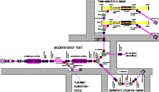
Fig. 1: The general layout of the ELBE beamlines
Space-charge effects on the electron beam transport
were studied using the Parmela [1] beam transport code.
Electron beams which should allow an FEL operation
can be supplied down to 10 MeV beam energy.
The longitudinal phase shift R56 increases
with decreasing energy from its design value
R56=93 mm at 20 MeV to R56=160 mm at 10 MeV
which has to be compensated for by tuning the chicane.
At the same time, the longitudinal emittance and
the energy spread of the beam are growing significantly.
At 10 MeV the longitudinal emittance already triples
but the beam quality still is just sufficient for
the FEL operation.
The electron beam transport to the radiation physics cave
has to be designed achromatic in order to conserve the
low transverse emittance of the beam. This is achieved
with a dispersion-crossover in the 45 deg section of the
beamline. This crossover is placed asymmetrically
in order to be situated outside the concrete wall and to
be accessible for beam diagnostics. The necessary focussing
is provided by quadrupole doublets before and after
the wall that separates the accelerator hall from
the radiation physics cave.
At the position of
the channeling target a beam waist is created which diameter
can be adapted to different experimental requirements.
Either large focal spot sizes with very low beam divergence
or rather narrow foci can be tuned using the two single
quadrupoles situated before the switching magnet and
after the first dipole in the radiation physics cave.
The actual position of the focus is variable as well,
thus allowing to use an alternative channeling
target downstream the goniometer chamber, which design
is optimized for the production of high-flux photon beams
but lacks some of the flexibility of the goniometer.
For the nuclear physics beamline the last dipole magnet
of the chicane is used in connection with one additional
dipole and a quadrupole in between to achromatically
deflect the electron beam by 45 degrees. A quadrupole
doublet provides the necessary focusing onto the
radiator target. A set of steerers is used to vary
the angle of incidence of the electron beam with respect
to the collimator axis, thus allowing experiments using
partially polarized bremsstrahlung radiation emitted
off the forward direction. The thickness of
the radiator is limited by electron scattering
and the according radiation background from electrons
hitting the tubing. Therefore, special attention has to be paid to
the design of the beam path from the radiator target
to the beam dump, which has to be as short as
possible and well shielded.
References
[1] L.M. Young, J.H. Billen, Los Alamos National Laboratory, LA-UR-96-1835
FWL
05/21/01
© U. Lehnert
|
