| First Beam Exposition of the HADES Drift Chamber MDCIII at SIS B,G,W | |||
|---|---|---|---|
| F. Dohrmann1, R. Dressler, W. Enghardt, O. Fateev2 E. Grosse, K. Heidel, K. Kanaki, R. Kotte, L. Naumann, M. Sobiella | |||
|
The HADES spectrometer including all major detector units, read-out, data-acquisition and trigger electronics has been tested in the commissioning beam time in November 2000. It consists of ring imaging Cherenkov counters, multiwire drift chambers (MDC) of planes I to III, time of flight scintillation hodoscopes (TOF) and pre-shower modules [1]. The first large-area drift chamber MDCIII for the third tracking plane produced at FZ Rossendorf was installed in sector four of the HADES spectrometer (Fig. 1).
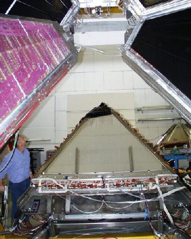
Fig. 1
MDCIII mounted on the support frame of the HADES spectrometer. Under normal working condition the drift chambers are hidden inside the spectrometer
core.
A 1.5 AGeV carbon beam with an intensity of 5x10⁶ per spill hits a carbon target. The spill length amounted to 5 seconds.
Most of the reaction products crossing the spectrometer were protons and pions.
Fig. 2
The analog signals monitored with a scope. The signals shown from top to bottom were measured on MDC planes I to III.
The applied high voltage amounts to -2 kV for both the cathode and field wires.
A selected anode wire is connected to an analog output to check the amplified signals as shown in Fig. 2.
The shape of the signal shows a risetime of 30 ns up to the saturation level of the preamplifier.
Fig. 3 Drift time distribution of leading electrons in one anode layer of MDCIII (0.5 ns/channel). The time measurement started by a common signal, created by the TOF trigger, and stopped by an individual anode signal.
Fig. 4
Two prongs of an event align between the target and the points of intersection in all three MDC's of sector four (bottom) of the HADES spectrometer.
Each prong is characterised by the
point of intersection of all fired signal wires in the two dimensional projection plane. The MDC plane numbers have been labeled by colors.
A stereo optical positioning system [2] monitors with a resolution of 1 mm the three dimensional displacement between
the MDC's before and behind the magnet.
The mean observed displacement during all runs was less than 10 mm.
1ANL, Argonne, USA
References
[1] http://www-hades.gsi.de
|