| Tests of the First HADES Drift Chamber MDCIII B,G,W | |||
|---|---|---|---|
| R. Dressler, W. Enghardt, O. Fateev1, E. Grosse, K. Heidel, J. Hutsch, R. Kotte, L. Naumann, M. Sobiella | |||
|
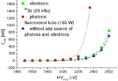
The final design of the large trapezoidal low-mass drift chambers (MDCIII) of the HADES spectrometer tracking system has been performed at the detector laboratory of the FZ Rossendorf [1]. These drift chambers consist of 6 modules with an active area of 2.20 m2 for each plane and a drift cell size of 8x12 mm2. Each module has 6 drift cell layers, i.e. 6 anode and 7 cathode frames. The anode frames contain alternately signal wires (tungsten gold-coated, Ø = 20 mm) and field wires (aluminium, Ø = 100 mm) with a distance of 6 mm from each other. The wires in the anode frames have orientations of -40°, +20°, -0°, +0°, -20° and +40°, respectively, whereas the wires in the cathode frames (aluminium, Ø = 80 mm) have always the same orientation +90° and a distance of 3 mm. Over the last two years we have solved all physical and technical problems of the design and production of the MDCIII. A full size prototype was finished in February 2000, consisting of only one anode frame (orientation +0°) between two cathode frames and in addition the other 10 frames without wires. Thus, the total volume of this prototype (150 l) matches the volume of a final MDCIII sector. A mixture of helium and iso-butan (60% He, 40% i-C4H10) was used for test measurements, which should be applied in real experiments. A stable gas mixture can be guaranteed by a flow of 10 l/h because the leakage rates of both gas components differ slightly (0.15 l/h at a level of 0.5 l/h). The results of first measurements are depicted in the following figures. Fig. 1. shows the current versus the high voltage. It is obvious to see, that external light sources (e.g. fluorescent tubes) dramatically reduce the break-through voltage, due to the emission of photo electrons from the Al wires.

Fig. 1 Current versus supplied high voltage for different working conditions.
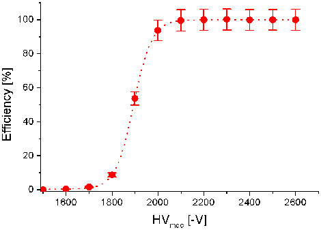
Fig. 2 Counter efficiency versus supplied high voltage for the prototype. The counting characteristic of the prototype is depicted in Fig. 2. A 90Sr source (50 kBq) was used to deliver electrons, which are additionally detected in a master scintillator telescope (20x20 mm2), a 1 mm thick scintillator in front of the prototype and a 5 mm thick scintillator behind. The signal from the anodes was amplified by a factor of 50 with a fast current sensitive preamplifier [2] and further processed with NIM and CAMAC modules. Up to a high voltage of -2600 V the prototype works without break through. A large counting plateau of 500 V was found above -2100 V. Nearly hundred percent counter efficiency was reached for the individual drift layers and a value of 98% was determined for coincident signals in all six drift layers.
1 JINR, Dubna, Russia
References
[1] http://www.fz-rossendorf.de/FWK/hp/hades.html
[2] K. Heidel et al., this Report
|
