|
To optimize and control the electron beam at the ELBE facility a comprehensive system of diagnostics has to be provided similar to other facilities such as CEBAF, TTF, S-DALINAC or MAMI. In general there are two types of diagnostics. For destructive diagnostics a special diagnostics mode of beam operation was defined in order to limit the dissipated beam power. Nondestructive diagnostics can be used at all times to monitor the full-power operation of the beam. The system of diagnostics at ELBE will contain the following components:

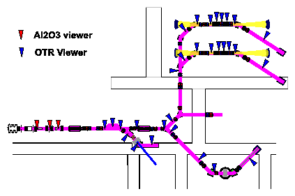
Fig. 1 ELBE beam viewers The beam viewers are operated in the diagnostics mode at an average beam current of about 1 mA and nominal bunch charge. The beam current is then controlled by the macro pulse parameters. The beam viewers are used to adjust the beam by optical inspection of the position and the size of the beam spot. Beam profiles can be determined using image analyzing software. In energy dispersive regions of the beamline viewers can be applied to measure the energy spread. In connection with multi slit masks or quadrupoles the transverse emittance of the beam can be measured. The described beam viewer concept was succesfully tested at the injector using the following equipment: screens - 500 mm Al2O3 ceramic (fluorescence) or 8 mm Al foil (OTR), cameras - Vidicon KH500 with Saticon tube XQ1300SF (radiation resistant), in some cases CCD cameras KAM02E, external target illumination, video multiplexing system (remote control) and a PCI-1407 frame grabber board which delivers at maximum 25 images/s synchronized to the macropulse. Beam position and beam current monitors
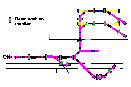
These monitors are realized as strip line monitors with the following details: 35 mm diameter, signal filter 1.3 GHz with 60 MHz band width, signal conversion using an AD 8313 logarithmic rms-to-DC converter chip (0.1 - 2.5 GHz; 70 dB) into a 12(16) bit ADC. One prototype of the proposed strip line monitor was tested at the injector. A spatial resolution of < 30 mm was achieved in the current range of 10 - 1000 mA. The analysis of the strip line monitor signal with respect to its time behaviour allows the measurement of the bunch length with time resolution < 100 ps. Thereby the strip line monitors can be used for optimization of the bunch compression in the injector to deliver an optimized beam to the accelerator section. Additionally to the strip line monitors information on the beam current can also be obtained at the various apertures and wall current monitors and at the beam dump. Martin-Puplett Interferometer (DESY-design)
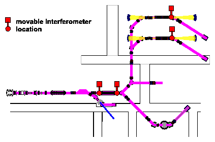
The interferometer serves for measuring the bunch length in the submillimeter range by measuring the autocorrelation function of the coherent transition radiation. Golay cells are used to register IR radiation, the bunch length is calculated by the Kramers-Kronig method. The assembly of the interferometer is finished. At present the software for analysis is being developed.
Beam loss monitors
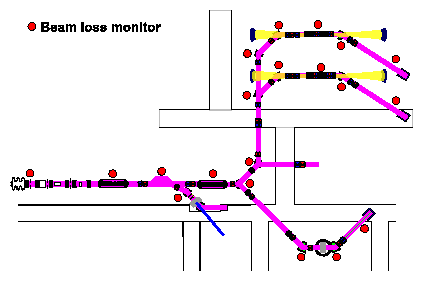
The aim of these monitors is to measure the beam loss at a number of positions to ensure full beam transmission and to have some protection against thermal and radiation damages. They consist of low cost photomultipliers (EMI9125) measuring bremsstrahlung radiation produced by electrons striking the beam tube and a count-rate integrator using VC 110 f/V-converter chips that deliver a radiation-dose signal into an ADC input. An optical test pulse will be used to ensure fail-safe operation. During tests at the injector this simple concept turned out to be fully efficient delivering signals proportional to the radiation dose.
|


