|
Beam dumps will be used to aborb the electron beam energy of the radiation source ELBE.
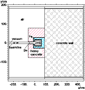
In the FEL cave it is planned to install the beam dump in front of a 3.6 m thick concrete wall
and to shield it by iron and heavy concrete. The planned thickness of the iron layer in beam
direction is about 30 cm resp. three tenth-value layer thicknesses of iron. For an axial symmetrically geometry (Fig. 1) the
absorbed dose has been calculated using the particle transport code
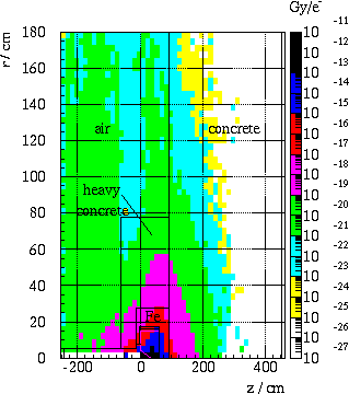
FLUKA [1]. The dose distribution in the described area for an electron beam with an energy of 50 MeV
is shown in Fig. 2.

|
|

|
|
Fig.1 : The placement of a graphite beam dump surrounded by iron and concrete
shielding in front of a 3.6 m thick concrete wall.
|
|
Fig.2 : The dose distribution for a cylindrical geometry at an electron beam with
50 MeV energy.
|
|
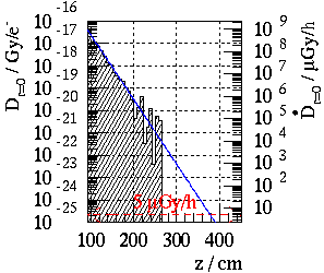
Assuming that the maximum dose is obtained along the beamline, the dose
distribution into the inner radial section has been extracted from the dose distribution
of Fig. 2. The dose distribution along the beamline inside the concrete wall (Fig. 3) has
been calculated up to a
depth of about 1 m with good statistics and the tenth-value layer thickness of the concrete
has been obtained to 34.9 cm. This value is in a good agreement with data given in
[2]. After passing the concrete wall the absorbed dose has been estimated
approximately to
1.6 · 10-27 Gy/e- and the dose rate to 0.04 mGy/h, which is two orders of
magnitude lesser than the
maximum value of dose rate for controlled areas  max = 5 mGy/h. max = 5 mGy/h.
|
|

Fig.3 : Dose and dose rate distributions along the
beamline axis z inside the concrete wall.
|
1Institut für Kern- und Teilchenphysik, TU Dresden
References
[1] A. Fasso et al., Proc. of the III Spec. Meeting on Shielding Aspects,
Sendai (1997)61-74.
[2] Report NCRP-51, Radiation protection design guidelines, Washington (1977).
IKH
06/01/01
© B. Naumann
|


 max = 5 mGy/h.
