|
Design and construction of the optical Cavity of a far infrared FEL
for the handling of long wavelengths is a great challenge.
Tab. 1 shows the optical cavity and mirror parameters
derived from the numerical simulations performed in [1] and [2]
for the propagation of the optical mode in the 11,5 m long optical
cavity using a partial waveguide within the undulator.
Table 1
| Resonator length | 11530.5 mm |
| Position shift of a mirror | 2 mm |
| Stability of the mirror distance | 1 mm |
| Distance resolution | < 0.5 mm |
| Increment | < 0.5 mm |
| Direction change hysteresis | < 0.5 mm |
| Angle error of the cavity mirror | < 5 mrad |
| Error of the mirror surface | 2 mm |
| Horizontal mirror diameter | 145 mm |
| Vertical mirror diameter | 270 mm |
| Mirror thickness | 25 mm |
| Horizontal radius of curvature | 5995 mm ± 0.25% |
| Vertical radius of curvature | 4585 mm ± 0.25% |
| Diameter of the outcoupling hole | 6 mm |
| Waveguide heigth | 10 mm ± 0.1 mm |
| Waveguide width | 40 mm |
| Waveguide length | 2360 mm |
| Waveguide surface roughness | 1...2 mm |
These parameters were determined by the following boundary conditions:
The partial waveguide within the undulator guides the optical
mode in the vertical direction through the narrow 20 mm magnetic gap
in form of a fundamental waveguide mode with cosine distribution. The
optical mode in horizontal direction has a Gauss-shaped
freely spreading mode form both within and outside of the
waveguide.
Due to this hybrid structure and the different
divergence of the optical mode in horizontal and vertical
direction outside the waveguides so-called bifocal concave toric
mirrors with an elliptical cross section have to be used.
As the outlet of the optical gap in the waveguide amounts to 10 mm,
the strong beam divergence in vertical direction results in a
necessary mirror diameter of 270 mm for a wavelength l = 150mm.
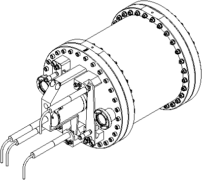
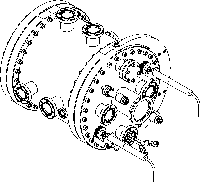
The mirror chambers have a diameter of about 300 mm. In fig. 1 and 2
they are shown with
the necessary assembly nipples for the diagnostic and servo units.
The outcoupling of the laser radiation is made by means of a centric
6mm hole in one of the cavity mirrors. Additionally a horizontal
insertable scraper mirror [3] should be able to outcouple a
variable part of the laser.
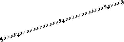
For the alignment of the magnetic axis of the undulator, the
electron beam axis and the axis of the optical cavity three insertable
Berillium viewscreens with a centric hole of 1 mm are used within
the waveguide (fig. 3).
The production technology for the waveguide is being verified by practical attempts.
The detail construction of the mirror chambers has started and the draft design and version comparison
of the optical cavity have been finished.
The dimensions of the scraper mirror and its vibration-free mounting are open problems.

Fig. 1 Mirror Chamber 1

Fig. 2 Mirror Chamber 2

Fig. 3
Wave Guide
References
|
[1]
|
R. Wünsch, FZR-276 (1999)
|
|
[2]
|
M. Tecimer and R. Wünsch, Losses in a Partial Waveguide Resonator of a FEL, this Report
|
|
[3]
|
R. Nagai et al., An Optical Resonator with
Insertable Scraper Output Coupler for the JAERI Far
|
|
|
Infrared Free Electron Laser, 22th Free Electron Laser
Conference, Durham, North Carolina,
August 13-18, 2000
|
FWF
05/22/01
© A. Wolf
|


