|
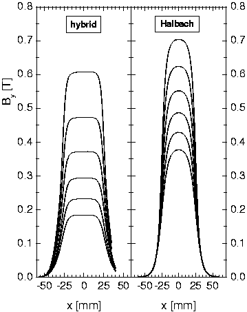
In an ideal undulator the magnetic field is assumed to be independent of the position in the wiggle plane (x-coordinate). In a real undulator consisting of finite magnets the field strength has a plateau in the center of the magnets (x = 0) and diminishes when moving toward their ends. The drop in the field strength defocuses the electron beam, i. e. electrons moving off the undulator axis and/or with a finite angle to it are deflected such that the beam size increases. To study this effect we have measured and calculated the field profile in the wiggle plane of our undulators. We noticed a significant difference between the hybrid configuration (U27) and the Halbach construction (U50) even though their magnet blocks have the same width (w = 50 mm). Fig. 1 shows the measured field profiles for either configuration for a variety of undulator gaps. Generally, the hybrid magnetic configuration has a much more pronounced plateau than the Halbach construction has. At gaps below 10 mm, the first even has a small dip at x = 0, which is too small ( < 1%) to be visible on the scale of fig. 1 
Fig. 1 Measured transverse magnetic field profile of a hybrid undulator (left panel) in comparison to a Halbach construction (right panel) for the gaps g = 10, 12, 14, 16, 18 and 20 mm (from top to bottom). For the Halbach construction, only g = 16 and 20 mm have been measured. The other profiles have been calculated using the code RADIA [1] with parameters fitted to the measured profiles. To investigate the effect on the electron beam we have calculated the average beam radius sx for either field configuration at the undulator exit for different gaps when starting with the same parallel beam of radius (0.4 mm) at the entrance. Fig. 2 clearly illustrates the pronounced defocusing effect in the Halbach undulator around a gap of 10 mm, in particular at lower energies. We also see the slight focusing action of the hybrid-type undulator at very small gaps. Note however that for a realistic simulation the beam divergence and the space charge have to be taken into account.

Fig. 2 Beam radius (rms) sx in the wiggle plane after passing the undulator in either configuration as a function of the undulator gap for three different beam energies (indicated). Left panel: hybrid undulator (U27); right panel: Halbach construction (U50). sx = 0.4 mm at the entrance. Code GPT [2]. 1 FOM Institute for Plasma Physics Rijnhuizen, The Netherlands
References
[1] P. Elleaume, O. Chubar and J. Chavanne, J. Syn. Rad. 5 (1998) 481-484
[2] Pulsar Physics, General Particle Tracer, http://www/pulsar.nl
|