Electron beam transport system and diagnostics
An s-shaped electron beamline to the permanent magnetic undulators was choosen because of the geometry of the building. This gives also rise to a bunch compression if the higher energetic electrons are earlier then the lower energetic ones.
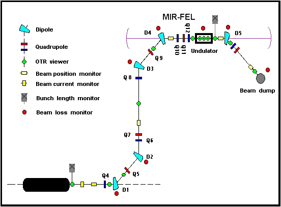
Fig. 1: s-shaped beamline to the permanent magnetic undulators
Electron Beam Transport System
The beam transport system, which guides the electrons from the accelerator hall into the upper cave of the free electron lasers is shown in fig. 1. Here, green symbols represent the dipole magnets (D), blue and red boxes the vertically and horizontally focusing quadrupoles (Q), respectively. The position of the FEL is indicated by a black rectangle, the second accelerator stage planned for a kinetic energy of 40 MeV by a black tank. The fig. 2 shows the horizontal and vertical beam enveloppes from the exit of the first accelerator stage (20 MeV) to the electron beam dump. The optical elements characterized by coloured stripes correspond to those explained in fig. 1.
Many advanced applications of the mid infrared FELs require short electron bunches with a bunch length in the region of 1 ps or even shorter. The s-formed bending system can be used to compress the bunches, since electrons with a momentum p+ = p0+dp (p0 characterizes the reference particle) exhibit a drift length longer than that of electrons with p- = p0-dp. To employ this fact for bunch compression, one needs a beam with a (dz,dp/p) correlation as shown in the upper part of fig. 3 (left panel). There, the ellipse (a) characterizes the beam in the longitudinal phase space at the exit of the accelerator system (notice, that dp/p is proportional to the instantaneous energy spread dE/E, whereas dz is proportional to the phase angle Δ&Fi; ). By careful adjustment of the quadrupole Q8 the electron bunches moving through the s-formed bending system are compressed. The (dz,dp/p) correlation is now represented by the erect ellipse (b). Thereby the bunch length dz is shortened from about 2.9mm( ≅9.6ps) to 0.4mm( ≅ 1.3ps), both values measured at the basis of the bunch. The right panel shows the beam spots before (a) and after compression and proper matching of the beam (b).The compressed bunches exist only on their drift path between the dipoles D4 and D5, as is demonstrated in the lower part of fig. 3.
The corresponding calculations were performed with the computer code MIRKO[1] for an electron energy of 19 MeV by taking into account space charge effects. Additionally, we simulated the behaviour of 1900 individual particles of the same energy using the code PARMELA[2]. The results of these simulations are shown in fig. 4, which compares the longitudinal phase spaces (Δ&Fi;,ΔE) of the electron bunch behind the first accelerator stage (left panel) and at the entrance of the FEL (right panel). A considerable compression can be obtained. Additional calculations have been performed for kinetic energies of Ek= 12 MeV and 15 MeV (fig. 5).
In order to obtain within the undulator a maximum overlap between the electron beam and the electromagnetic field accumulated in the optical resonator, the beam should be matched to the beta function of the undulator [3]. Using the codes MIRKO and PARMELA, we simulated the undulator U27 by an arrangement of single dipols with proper geometrical parameters and field strengths[4].
Further details of these calculations are presented in ref [4].
[1] B.Franczak, GSI Darmstadt, MIRKO, Version 6.06, 1998
[2] L.M.Young,J.H.Billen, Los Alamos National Laboratory,LA-UR-96-1835
[3] W.A.Gillespie et al., NIM A250(1986)233
[4] P.Gippner, Annual Report 1998/99, FZD-271,p.15
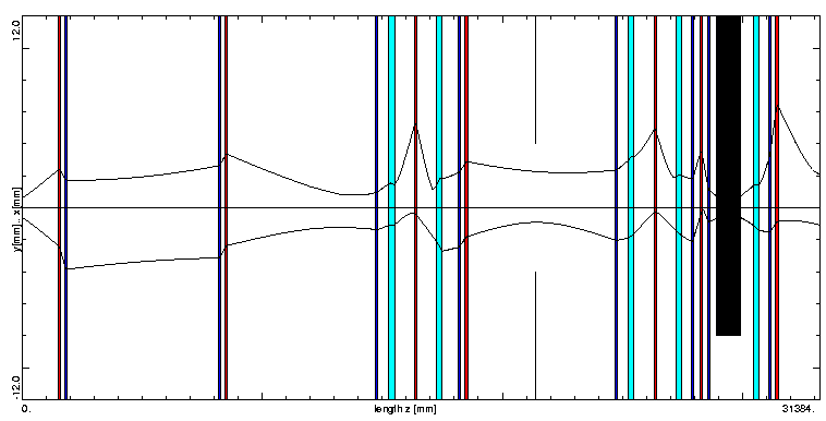
Fig. 2: The horizontal (x) and vertical (y) beam enveloppes in dependence on the coordinate z, assuming a kinetic energy EK=20.0 MeV and geometric emittances εx=εy=0.45 mm · mrad
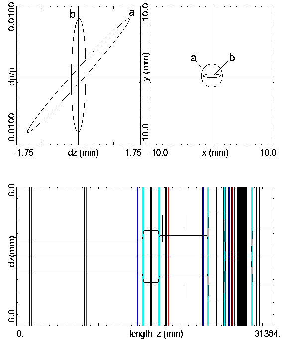
Fig. 3: The ellipses in the longitudinal phase space and the beam spots before(a) and after compression(b) (upper part). The bunch length dz as a function of the length z in the beam system (lower part).
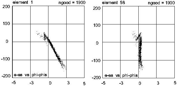
Fig. 4: Bunch compression for a beam of EK=19.0 MeV kinetic energy.
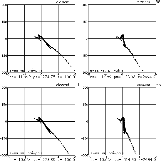
Fig. 5: Bunch compression for a beam of EK=12.0 MeV (upper part) and EK=15.0 MeV (lower part)
Electron Beam Diagnostics at the FEL
Electron beam diagnostics in a Free Electron Laser facility need similar instrumentation as those of almost any electron accelerator. On the other hand, the beam parameters should be optimized to get high and stable laser gain, which requires specific diagnostic tools and leads to a different emphasis than usual, such as very short bunch length, the beam β -funktion in the wiggler, and low average beam loss. The ELBE-FEL electron beam diagnostics should enable to setup the accelerator and beamline elements for a certain lasing mode and to monitore parameter changes during lasing runs. The most important parameters for optimum lasing conditions are beam location, beam profile and bunch length inside the undulator, respectively.
Undulator beam viewer
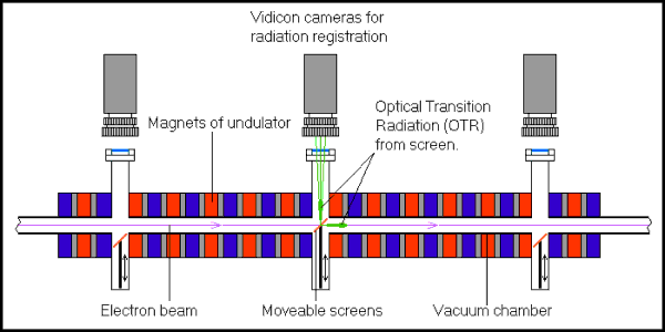
For a good FEL operation, the electron beam center and the optical resonator axis must overlap. Moreover, the size of the electron beam has to be matched. Both requirements are needed to maximize the undulator filling factor, which is essential for lasing. To verify the electron beam geometry inside the undulator, we plan to measure the beam size and position at three locations by means of OTR viewers.
Bunch length monitor
To optimize the electron bunch length for lasing, it will be measured near the wiggler. For this purpose, the transition radiation will be deflected into a Martin Puplett interferometer. The coherent transition radiation spectrum at long wavelength (50 μm to 1mm) can be measured, and the electron bunch length as well as-under certain conditions-the longitudinal bunch distribution can be derived. The Martin Puplett interferometer has been developed at the RWTH Aachen and the DESY Hamburg /1/ and built in Aachen in collaboration with FZ Dresden-Rossendorf.
Martin Puplett interferometer

