Kontakt
Dr. Ronald Schwengner
wissenschaftlicher Mitarbeiter
Kernphysik
r.schwengner![]() hzdr.de
hzdr.de
Tel.: +49 351 260 3332
Collaborations
The bremsstrahlung facility at the ELBE accelerator
 Photon-induced nuclear reactions
|
Photons of high energy (g quanta) can excite nuclear states. Since the photons transfer mainly spin 1 and, to a lesser extent, spin 2, low-spin states are excited. These states deexcite by emitting g transitions of discrete energies - according to the spacings between the excited states and lower lying states (see schematic figure). As this emission is induced by a photon of the appropriate (resonant) energy, the process is called "nuclear resonance fluorescence". The properties of the g transitions allow the quantum numbers of the excited states to be deduced:
|
 |
|
The excited states with spin J = 1 are referred to as "dipole excitations". These excitations may involve collective excitations of the nucleus such as vibrations. The study of these excitations and the discovery of so far unknown types of nuclear motion is important for the understanding of many-body quantum systems, which play a role also in other fields of modern physics, e.g. in solid-state physics. |
Experiments with bremsstrahlung
|
In order to realise the reactions described above, an intense photon beam with a continuous energy spectrum is needed. Such a beam is delivered by bremsstrahlung, which is produced if an electron beam hits an appropriate material ("radiator"). The electrons slow down in the material and lose their energy either by ionisation or by emission of radiation. For our experiments, we use the electron beam of the superconducting linear accelerator ELBE at the FZD with a maximum electron energy of 20 MeV. |
The bremsstrahlung facility at the ELBE accelerator
|
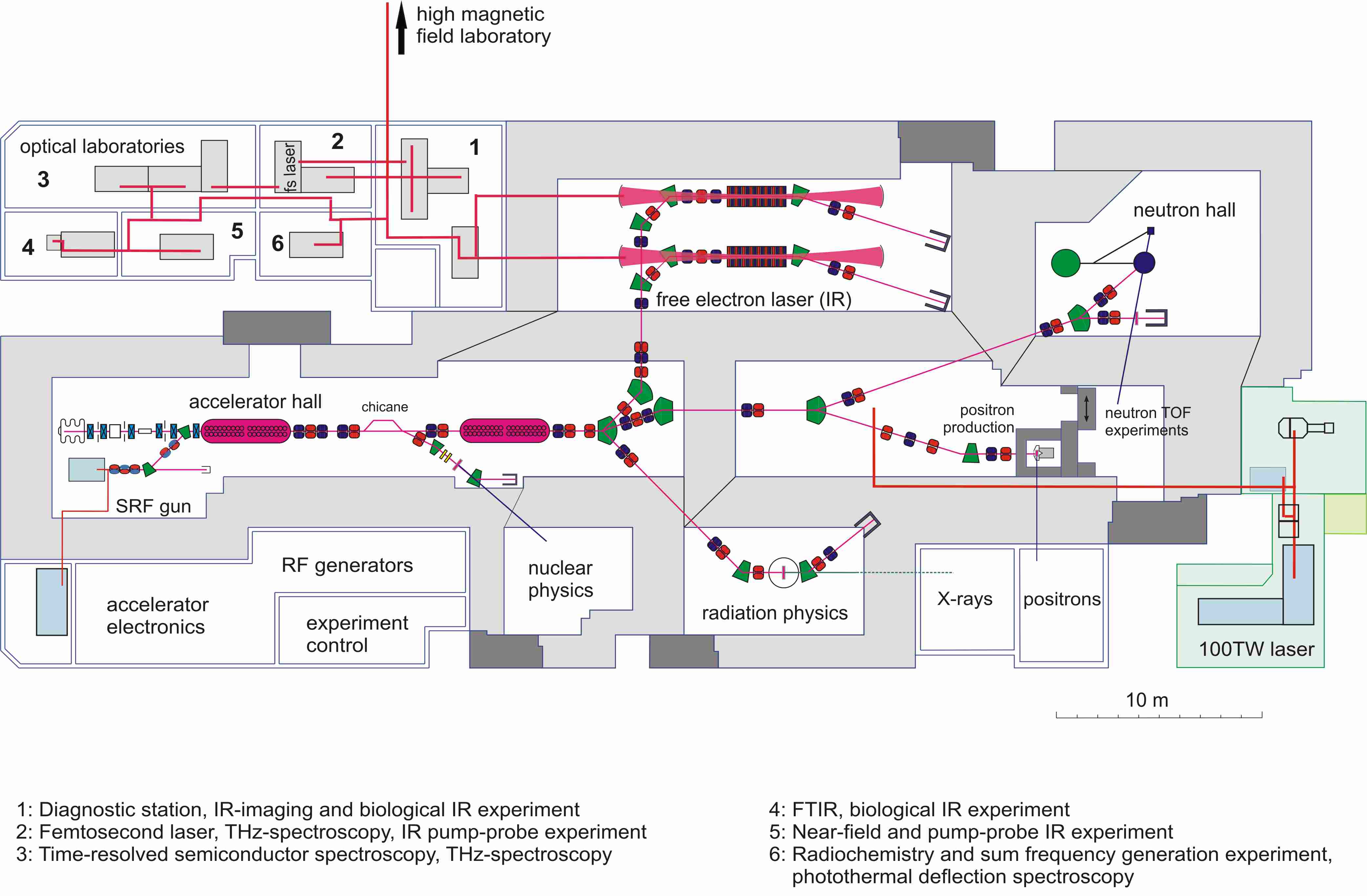
The bremsstrahlung facility at the ELBE accelerator is located in the centre of the floorplan between the first and second accelerator modules and in the experimental hall for nuclear physics.
The following figure shows a more detailed view of the bremsstrahlung facility. |
 The electron-beam line
|
The electron beam is lead out of the main beam line by a non-dispersive system of two 22.5o dipole magnets and a quadrupole magnet in between. A doublet of quadrupole magnets focuses the beam on to the radiator (the blue-red yoke of one of them is visible at the right border of the figure below. The following doublet of dipole magnets (steerers) will be used to produce a beam of polarised photons (see below). The radiator (within the chamber in front of the dipole magnet with the blue yoke) converts only a small fraction of the electron current to radiation. The main part passes through the dipole magnet, where it is deflected by 45o and is subsequently stopped in the electron beam dump made of graphite. This beam dump is surrounded by the stainless vacuum vessel within the yellow-painted iron shielding. 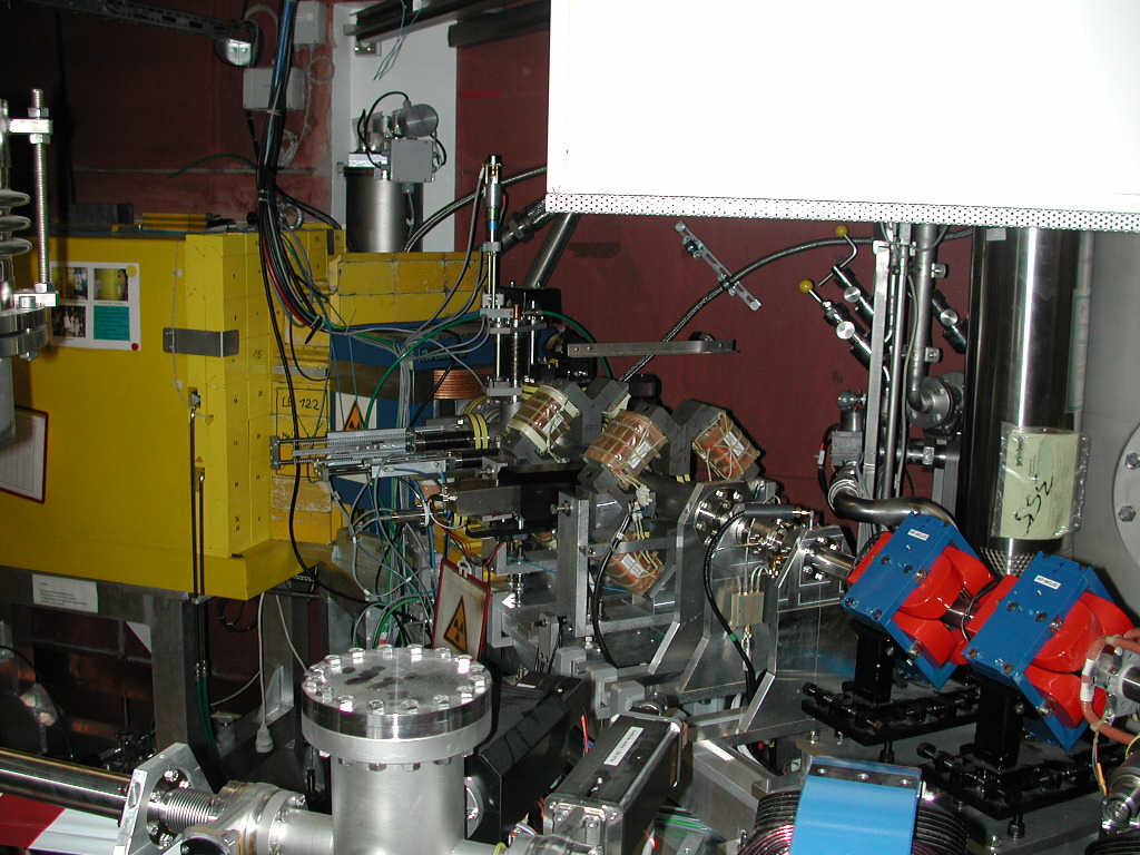 |
The radiator
|
The radiator consists either of a thin niobium foil with a thickness between 2 and 12 mm. A water-cooled holder of copper with six positions for radiators of 16 mm diameter is used (see figure below). This allows us to switch between different radiators without breaking the vacuum. The radiator is described in detail in the Annual Report 2002, p. 30.  |
The collimator
|
The collimator produces a beam of limited diameter from the spatial distribution of the bremsstrahlung photons. In our case, the collimator is placed in the wall of heavy concrete between the accelerator hall and our experimental cave. The collimator starts at a distance of 972 mm behind the radiator and has a length of 2600 mm (see figure). The drill-hole is conical and has a diameter of 5 mm at the entrance and 24 mm at the exit. In order to minimise the production of neutrons, the collimator has been made of pure aluminium, which has a relatively high neutron-separation energy of Sn = 13 MeV. Further details of the collimator are described in the Annual Report 2001, p. 37.  |
The beam hardener and shutter
|
The beam hardener and shutter shown in the figure is placed in front of the entrance of the collimator and consists of a cylindrical housing which contains 3 cylinders of aluminium (Al), carbon (C) and tungsten alloy (W), respectively (see figure). These cylinders can be moved vertically such that one or none of them is located in front of the collimator. The aluminium and carbon cylinders absorb mainly low-energy photons while they influence the high-energy part of the spectrum only to a small extent. In this way, they "harden" the photon spectrum. The tungsten cylinder is to shut the collimator. This allows us to work in the experimental cave while the accelerator is running for experiments in other caves. For further details see the Annual Report 2001, p. 41.  |
Production of polarised bremsstrahlung
|
In order to deduce the parity of the excited states (see top of page), it is necessary to measure the linear polarisation of the g transitions. The knowledge of the polarisation enables a discrimination between electric and magnetic multipole radiation, in our case mainly between electric dipole (E1) and magnetic dipole (M1) transitions. For this purpose, we will irradiate the target with polarised bremsstrahlung. The method used to produce polarised bremsstrahlung is shown in the figure. It makes use of the fact that the electric vector of the radiation goes tangentially around a cross section of the spatial distribution of the photons (see figure). Using the steering magnets mentioned above and described in the Annual Report 2002, p. 31, the electron beam will be deflected from the normal direction and then deflected back such that it hits the radiator in the centre under a particular angle Qo. As a consequence, an off-axis portion of the spatial distribution of the photons is cut out by the collimator. This off-axis portion of the bremsstrahlung cone is dominated by a definite direction of the electric vector, which means that the photon beam passing through the collimator is partly polarised. The degree of polarisation depends on the angle Qo and has a maximum at Qo = moc2 / E, where moc2 = 511 keV is the rest energy of the electron and E is the energy of the incident electrons.  |
The polarisation monitor
|
During long-time measurements it is important to monitor the degree of polarisation of the photons. This can be done via the photodisintegration of the deuteron. Because of predominant E1 absorption in this process the protons and neutrons are emitted preferentially in the direction of the electric field vector of the polarised bremsstrahlung. The energies of the incident photons correlate with the measured proton energies. The degree of polarisation can be deduced from azimuthal asymmetries of the intensities of the protons.  |
The HPGe-detector setup
|
The detector setup shown in the photograph below contains 4 high-purity germanium (HPGe) detectors. Two of them (top and bottom) are positioned perpendiculer to the photon-beam direction, while the two horizontal ones can be moved between angles of 90o and 127o relative to the photon beam. In this way the setup can be used either to measure azimuthal asymmetries of the g-ray intensities in experiments with polarised bremsstrahlung or to measure angular distributions of the scattered g rays. 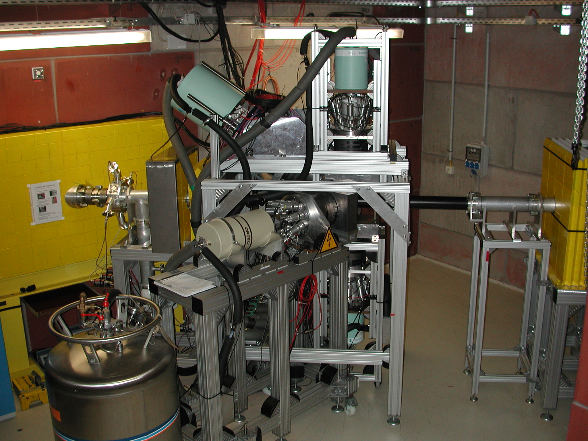 |
The collimator and escape-suppression shield for the HPGe-detectors
|
All HPGe detectors are surrounded by escape-suppression shields. These shields consist of 8 optically separated bismuth germanate (BGO) scintillation detectors arranged in a cylindrical shell and each read out by a photomultiplier tube. The BGO shields with the photomultipliers can be seen in the above photograph. The BGO shields are to register g rays which escape after Compton scattering or pair creation in the HPGe detector and, thus, contribute to the background in the HPGe spectra. The suppression of such events is realised by an anticoincidence between HPGe detector and BGO shield. In order to prevent the BGO detectors from direct hits by g rays emitted from the target, the front side of the BGO shield is covered by a lead collimator. This collimator and the front part of the BGO shield with the HPGe detector inside are shown in the drawing below. See also the Annual Report 2002, p. 24 and 26.  |
The photon-beam dump
|
The photon-beam dump is shown in the figure below. This beam dump was designed such that the backscattering of photons towards the detectors is minimised. The beam dump consists of an trapezoidal absorber block of polyethylene (PE) with a front side of 80 cm X 80 cm and a length at the beam axis of 100 cm. This inner absorber is surrounded by 0.5 mm thick sheets of cadmium and a lead housing with a thickness of 20 cm at the front and 10 cm at the sides. For details about the choice of the materials see the Annual Report 2000, p. 40. 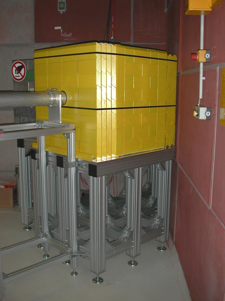 |
IKH 14/03/08 © Ronald Schwengner

