The Automated Complex for Investigating Hydrodynamics and Heat Transfer
for a Liquid Metal Flow under Magnetic Field with an Opportunity of the Remote Access
V.G. Ghilin, V.G. Sviridov*, Yu.P. Ivotchkin, N.G. Razuvanov,
L.G. Genin, E.V. Sviridov*, A.V. Ustinov* and V.S. Igumnov
IIHT - Incorporated Institute of High Temperatures of the Russian Academy of Science ,
Moscow, Igorskaya str.,13/19
* MPEI - Moscow Power Engineering Institute, Moscow, Krasnokazarmennaya str., 14
The joint experimental complex are put into practice as a result of scientific co-operation between IIHI and MPEI. The complex make it possible to begin with joint program of MHD liquid metal (LM) heat transfer investigations applied to fusion TOKAMAK reactor. The complex consists of two experimental MHD facilities. The first one installed at MPEI is a LM (mercury) loop for investigations of hydrodynamics and heat transfer affected by LONGITUDINAL magnetic field (MF). The second facility at IIHI is generally the same LM loop in TRANSVERSE MF. Both facilities are automated. The specific feature of joint automated system: on the base of "Virtual Instruments" technology it enables the user to make experiments both directly at the facility or reportedly under conditions of remote computer access via LAN or Internet. We consider this approach to give wider opportunities for international scientific co-operation.
Various sensors and transducers were used at different stages of works, namely: microthermocouples, special film thermoanemometers for LM, optical fiber probes, correlation-type velocity sensor, electromagnetic velocity sensors. Two- and three-dimensional local measurements in the LM flow are available.
The current experimental program deals with temperature fields, local and averaged heat transfer intensities in a horizontal heated tube both in longitudinal and transverse MF applied to TOKAMAK regimes of heating are considered:
1) uniform wall heat flux distribution along the tube perimeter: q1= q2= const;
2) non-uniform heating - heat flux on the left half of the tube is grater than the right one:
q1 > q2
3) one-side heating - only one half of the tube is heated: q1 º
0; q2 = 0.
The Reynolds, Hartman and Rayleigh criteria were as follows: Re = 5000¸
120000; Ha = 0¸
500; Ra = 0¸
3×
106.
Some results of these current experiments are presented below:
- The thermogravitational convection (TGC) affects LM heat transfer in a tube. Depending on the MHD-configuration, MF can enhance or weaken this effect (Fig.1). As a result of TGC affect local heat transfer intensity changes significantly along the tube perimeter. The zones with enhanced (at a bottom of a tube) and poorer (at a top) heat transfer intensities arise. The longitudinal MF makes these non-uniformity grater, while the transverse MF - smaller.
- The TGC affect results in the appearance of secondary motion. The direct vertical components of the velocity measurements (Fig. 2) show the existence of one or two secondary vortices with axes parallel to main flow direction. Longitudinal MF make these vortices more stable. Due to secondary motion the perimeter-averaged heat transfer intensity in MF can be even larger then without a MF.
- Depending on the combination of electromagnetic and buoyancy forces acting on the flow, the turbulent velocity or temperature fluctuations (Fig.3) can be suppressed or increased. In some MHD configurations the regimes were found with abnormally high temperature fluctuations in a near-wall region. These fluctuations can be dangerous: on penetration into the wall they can cause high thermal stresses and fatigue failure of the wall material.
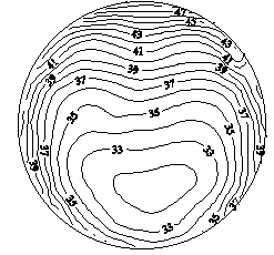
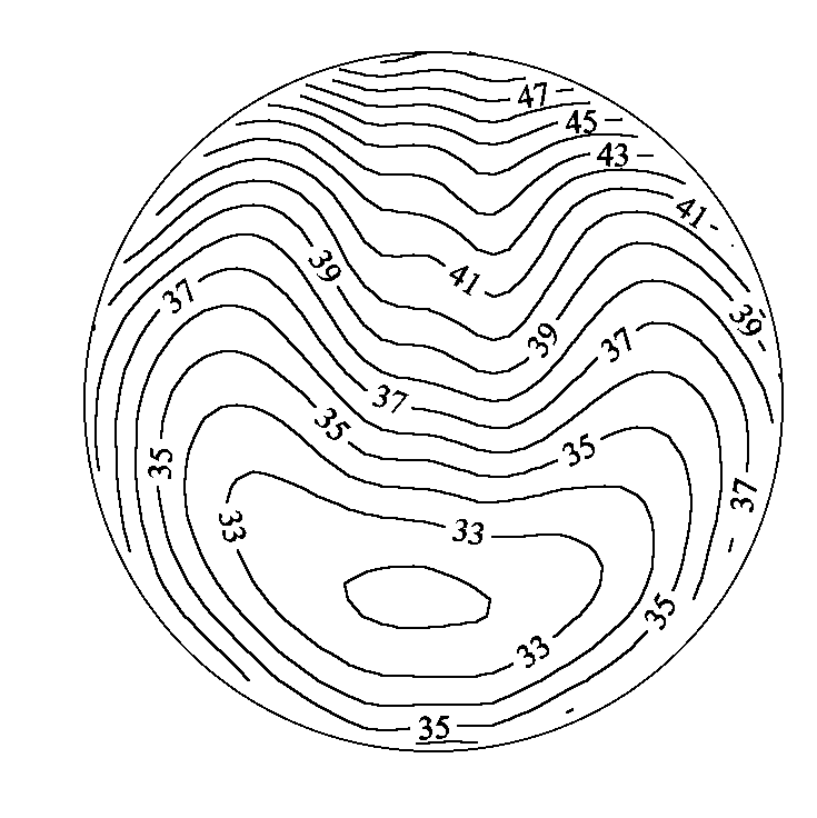
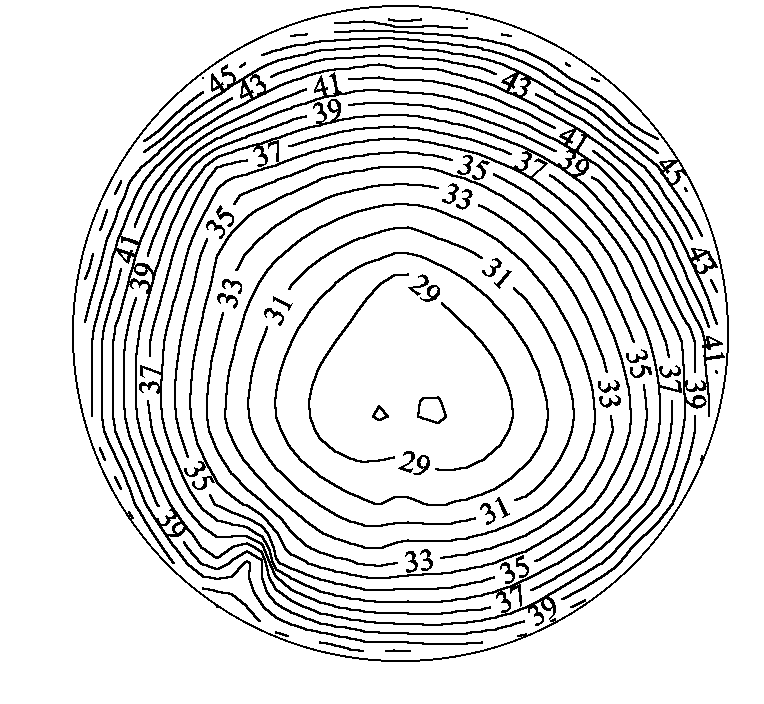
a) Without a magnetic field; b) in longitudinal MF; c) in transverse MF
Fig. 1: Mean temperatures in a cross-section of horizontal pipe. Uniform heating
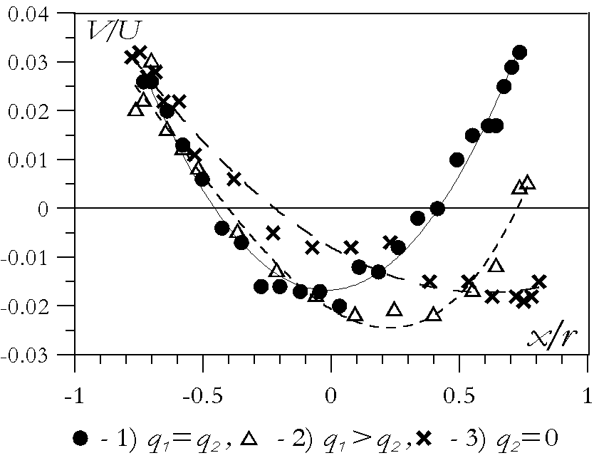
Fig. 2: Secondary motion - vertical velocity profiles (V - vertical velocity, U - mean
velocity)
Re = 3500, Ha = 450, Heating regimes: q1 = const. = 35 kW/m2,
1) q2 = 35 kW/m2,
2) q2 = 15 kW/m2,
3) q2 = 0 kW/m2
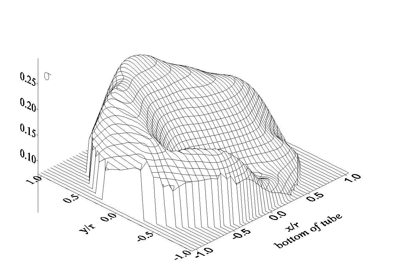
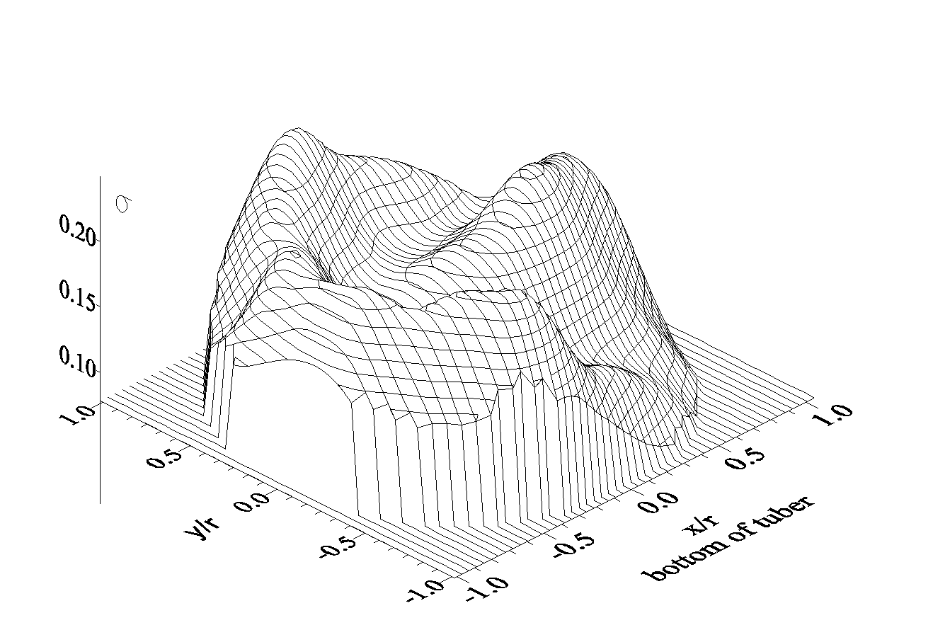
Fig. 3: Temperature intensity in tube cross-section (non-uniform heat flux q1 = 35 kW/m2,
q2 = 15 kW/m2; Re = 24000): a) Ha=0, b) Ha=300.
back to the workshop programme


