Measured Parameters of the ELBE Electron Beam
1. Beam Parameters of the ELBE Accelerator
2001 was a decisive year for the ELBE radiation source. All components belonging to the first stage of ELBE were successfully put into operation. The main beam properties were measured and it was shown that all major design parameters of the ELBE accelerator could be reached. All measurements are in good agreement with previous simulations. As a consequence of contamination of the superconducting cavities, the achievable accelerating gradient, particularly in the second cavity, was reduced. Therefore, beam parameters such as bunch length and emittance were measured at 12 MeV beam energy instead of the previously reched 20 MeV.
The following table shows the main parameters measured during year 2001.
| maximum beam energy |
20 MeV |
| maximum bunch charge |
77 pC |
| maximum beam current |
0.85 mA at 12 MeV |
|
| |
at 1 pC
bunch charge |
at 77 pC
bunch charge
(combined) |
at 77 pC
bunch charge
(separate) |
energy spread
transverse emittance
bunch length |
35 keV
3 p mm mrad
- |
55 keV
10 p mm mrad
2.5 ps |
40 keV
8 p mm mrad
2.0 ps |
|
2. Bunchlength Measurements
The electron bunch length at ELBE is in the picosecond range. Such bunch length corresponds to a THz bandwidth. This makes direct electrical measurements impossible because the bandwidth of cables and waveguides is not high enough. During commissioning of the first ELBE acceleration module the electron bunch length was measured using a coherent transition radiation (CTR) technique. Here are the key issues of this technique.
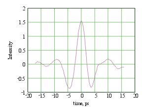
The transition radiation is produced when electrons pass a boundary of two media with different dielectric constants. The response time of the transition radiation is zero. Due to this fact the longitudinal shape of the radiation pulse is a copy of the electron bunch shape. In the measurements a Martin-Puplett interferometer (MPI) [1] is used to measure the autocorrelation function of the CTR pulse (see Fig. 1). Than, the power spectrum of the electron beam can be calculated and compared with the spectrum of a beam of a suspected shape and size.
 |
Fig. 1: Interferogram obtained by scanning the time delay between the two optical paths of the interferometer. |
A 10 µm thick aluminum foil streched over a frame was used to produce the CTR. The view screen is oriented 45° to the beam direction. Thus the backward CTR is propagating perpendicular to the electron beam. We have used crystal-quartz window for the output of the CTR from the beam line. An interferometric technique was already successfully used at TTF for the electron bunch length measurements [2]. We have modified the interferometer with the goal to use Golay cell detectors instead of pyro detectors, which are used in the original design. A video camera was also installed at the interferometer so that we could see the size and the position of the electron beam on the view screen.
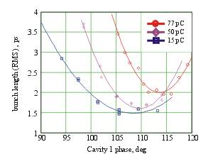
Bunch length behavior was studied at different bunch charges as a function of RF field phase in the first accelerating cavity. The first cavity determines the bunch length since the electrons become relativistic there and then bunch length remains constant. The bunch length was measured to be minimum 2 ps RMS at 77 pC bunch charge. Fig. 2 shows the results of the measurements. The results are in good agreement with PARMELA simulations.
 |
Fig. 2: Bunch length vs. phase of the first cavity. |
3. Emittance Measurements
For many applications of the ELBE electron beam the transverse emittance is a crucial parameter. For radiation physics experiments a very low transverse emittance is required to allow as many electrons as possible to become trapped into channeling states when entering a crystal. The operation of free-electron lasers puts some requirements on the transverse emittance as well in order to acchieve a good overlap between the electron beam and the optical mode over the whole length of the undulator.
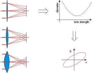
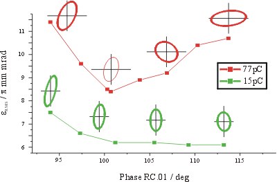
| Therefore, the transverse emittance of the ELBE electron beam was measured for typical bunch charges and for varying settings of the main accelerator controls. All measurements were done at 12 MeV beam energy using the quadrupole-scan method which is illustrated here. Basically, this method applies a variable lens (in this case a magnetic quadrupole) and detects the focal spot diameter on a viewscreen. From the dependence of the focal spot diameters on the strength of the lens the complete first-order parameter-set describing the transverse phase-space of the beam can be derived. So, Fig. not only shows the measured emittance for varying RF-phase of the first accelerator cavity but also displays the estimated phase space ellipses to show correlations within the beam. |
 |
 |
Fig. 3: Normalized transverse emittance of the ELBE electron beam for two different bunch charges measured with the quadrupole scan method at 12 MeV beam energy for varying RF-phases of the first accelerator cavity. |
Such emittance measurements have been done for several bunch charges ranging from 1 pC to the FEL-mode at 77 pC. In all cases the measured values agree well to those previously measured at the ELBE injector using a pepper-pot mask. This indicates that the emittance growth during the beam capture into the RF-field of the first cells of the cavity is negligible. A normalized emittance of less than 3 p mm mrad was measured at 1 pC bunch charge which could be cut down even further for radiation physics experiments using apertures in the injector. At full bunch charge the best measured values were below 8 p mm mrad. However, for FEL operation the accelerator controls have to be set to meet some compromize between best transverse emittance and the requirements of a low energy spread and a short bunch length. In this case 10 p mm mrad can be reached.
[1] P. Michel, P. Piot: FZD Annual Report 1999 Institut of Nuclear and Hadron Physic, 9
[2] M. Geitz et al., Proceedings of the 1999 Particle Accelerator Conference, New York, 1999, 2172-2174


