Laser-Induced Spectroscopy
General Principle
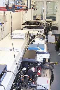 In principle the laser-induced spectroscopy is comparable to the other methods of optical spectroscopy. The (monochromatized) light of a light source is applied to a sample and emitted signals will be measured.
Lambert-Beer's Law
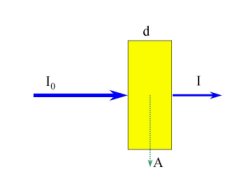
For calculations, Lambert-Beer's law is used:
log (I0 / I) = log(A) = E(x,w) * d * c
| I0 | Intensity of the applied light |
| I | Intensity of the not absorbed light |
| A | Absorption of light by the sample |
| E(x,w) | Absorption coefficient of the species x at the wavelength w (in UV-Vis spectroscopy = molar decadic extinction coefficient) |
| d | thickness of the sample |
| c | concentration of the species x in the sample |
Conventional spectroscopy measures I0 and I, whereas laser-induced methods measure the signal A directly.
In laser-induced spectroscopy the signal A depends on I0 under the condition that I0 is approximately equal to I. The measured signal A will be divided by I0 (measurement of the applied energy).
Scheme of the excited terms of the uranyl ion as a basis of spectroscopic studies in the uranyl system
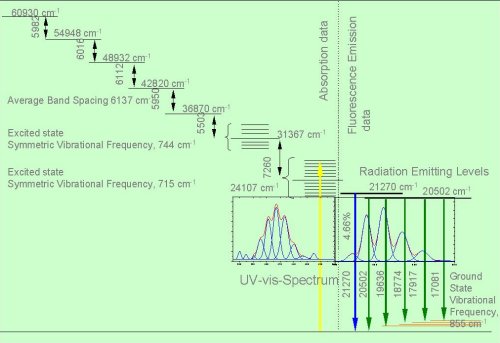
Ref.: Bell, J.T. and Biggers, R.E.
Absorption spectrum of the uranyl ion in perchlorate media III.
J. Molecular Spectroscopy 25, 312 (1986)
Methods
Laser-Induced Photoacoustic Spectroscopy (LIPAS)
- a method which allows to determine light absorbing species in solution, comparable to conventional UV-Vis spectroscopy, but without the addition of reagents which can disturb the chemical system;
- the detection limits of this method are normally three orders of magnitude lower than in UV-Vis spectroscopy.
The next figure shows the schematic experimental design. 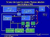
The sample to be studied will be excited by a monochromatic laser pulse at a desired wavelength. The species in the solution absorb a small amount of this laser pulse (excitation). After the laser pulse, the excited species in the solution emit the absorbed energy (reaching the ground level). The emitted energy leads to a small, local warm up in the solution, which cause an expansion. Because this expansion is very limited in time and volume, it travels as a pressure wave in the solution. This pressure wave can be measured by a piezo-ceramic detector which transforms the pressure wave into an electrical signal. This signal is directly proportional to the light absorption of the solution at the desired wavelength. By scanning over an adjustable wavelength range, the absorption spectrum of the species in solution can be measured.
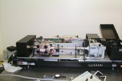 At the Institute of Radiochemistry a very modern tunable solid state laser is used for this method. It is pumped by a Nd:YAG Laser at the third harmonic (355 nm).
Using this solid state laser (the figure shows the opened system with the amplifier in the foreground) it is possible to cover the wavelength range from 220 nm to 690 nm and from 730 nm to 1800 nm. 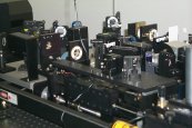 As examples you can download a picture of the firing laser at 500 nm and at 440 nm (using the frequency doubling option FDO, the output is at 220 nm). There are possibilities to couple the laser pulse directly into the cuvette. Moreover, a fiber optic system can be used to carry out studies in glove boxes.
Example: Complex formation of uranyl ions with carbonate ions
The formed complex UO2(CO3)34- is a non fluorescent uranyl compound and therefore its direct determination is only possible with UV-Vis- and Laser-Induced photoacoustic spectroscopy.
The formation constant for the reaction
UO22+ + 3 CO32- == UO2(CO3)34-
has been determined in the concentration range of UO22+ from 1x10⁻⁵ to 5x10⁻⁴ M. It was calculated to log k = 21.57 ± 0.70. This value is in good agreement with the data of the NEA-database, where the constants are determined at much higher uranium concentrations.
The next figure shows an absorption spectrum in the system UO22+ - OH- - CO32-, obtained by Laser-Induced Photoacoustic Spectroscopy under the conditions of 1x10⁻⁴ M UO22+ ; 5x10⁻³ HCO3-/CO32-; and pH 8,5.
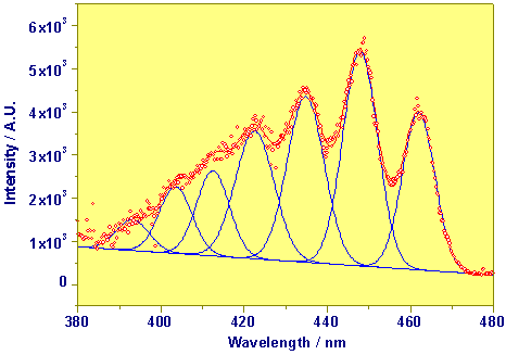
Photoacoustic Absorption Spectrum of UO2(CO3)34-
These studies have practical consequences at the direct detection of species in the environment. The following figure shows the laser-induced photoacoustic spectrum of a tailing water from an ore dressing facility. Here it was possible to detect the uranyl tricarbonato complex (concentration 2.5x10⁻⁵ M) in the solution.
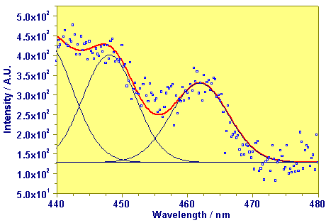
Photoacoustic Absorption Spectrum of Tailing Water
Ref.: G.Geipel, V. Brendler, G. Bernhard, and H. Nitsche. Complex Formation between UO22+ and CO32-: Studied by Laser-Induced Photoacoustic Spectroscopy. Radiochim. Acta, 82, 59, (1998)
Time-Resolved Laser-Induced Fluorescence Spectroscopy (TRLFS)
The excitation of the species in solution takes place in the same way as in Laser-Induced Photoacoustic Spectroscopy (LIPAS). A difference exists for the moment only in the fact that the studied sample (e.g. UO22+; Cm3+, Eu3+) will be excited at a fixed wavelength ( for instance the fourth harmonic of the Nd:YAG laser). Like in LIPAS, the energy of the laser pulse will be absorbed. During the following transition of the excited species to the ground state, the emission of heat is accompanied by the emission of photons from definite energy levels. Because the complex formation of the metal influences these energy levels, it is possible to determine the complex species in the solution using the spectral distribution of the fluorescence light. The emission of fluorescence decreases after the excitation following an exponential decay law. The decay constant also depends on the species in solution, therefore it is possible to determine two specific information with this method, which allow at least to study systems with several components.
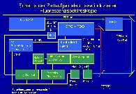 The scheme of the experimental set-up of Time-Resolved Laser-Induced Fluorescence Spectroscopy is shown in the accompanying figure.
The solution in the cuvette is excited by the applied laser pulse. Using a spectrograph, the fluorescence light from the sample is resolved into its intensities depending on the wavelength. To detect these intensities an array of photodiodes is used, which allows the detection of the complete fluorescence spectrum simultaneously. To expose the diode array only during a definite and adjustable time, a gated intensifier is located between the spectrograph and the diode array. The exposition time (gate) and its delay relatively to the applied laser pulse is managed by a delay generator using the data acquisition software. Thus, a series of fluorescence spectra can be collected, which differ from each other by a time difference relatively to the laser pulse. A photo shows the experimental set-up for the fluorescence measurements.
Example: Complex formation in the system Uranyl-Sulfate-Water
A time resolved fluorescence spectrum of exiting species in the system uranyl-sulfate-water is shown in the figure. The decrease of the fluorescence intensity as function of the time difference to the applied laser pulse can be seen.
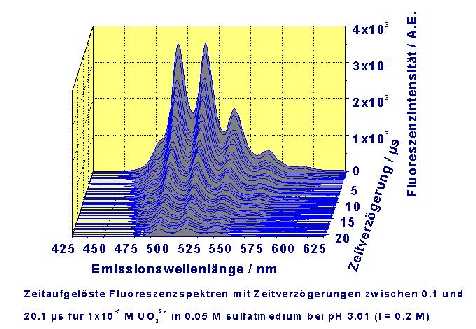
Time Resolved Fluorescence Spectrum of the Uranyl-Sulfate-Water System with Delay Times Between 0.1 and 20.1 µs, at 10-5 M UO22+ and 0.05 M Sulfate (pH = 3.01, I = 0.2 M)
Because in the acidic pH range there are up to four species possible in the system Uranyl-Sulfate-Water (UO22+, UO2SO4(aq.), UO2(SO4)22- and UO2(SO4)34-), several series of spectra have to be measured. Unfortunately the emission spectra of the several uranyl sulfate species show only small differences in their spectral distribution. Therefore the identification of the species is only possible through the fluorescence lifetimes.
The following table summarizes the fluorescence lifetime of the species at an ionic strength of I = 1 M.
| Species | Fluorescence lifetime / µs |
|---|---|
| UO22+ | 2.7 ± 0.3 |
| UO2SO4(aq.) | 4.3 ± 0.5 |
| UO2(SO4)22-(aq.) | 11.0 ± 1.0 |
| UO2(SO4)34-(aq.) | 18.3 ± 1.0 |
The following figure shows the fluorescence decay at several sulfate concentrations. The points represent measured values, the lines are the result of fitting with exponential decay functions using the fluorescence lifetimes as decay constants.
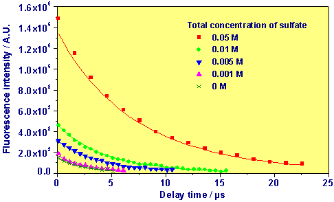
Accumulated Fluorescence Signal as Function of Delay Time of 1x10⁻⁵ M UO22+ at pH 2 (I = 1.0 M) and Several Concentrations of Sulfate
The concentrations of the various species were calculated from the results of the fluorescence measurements. The complex formation constants were calculated using these concentrations. The extrapolation to the ionic strength I = 0 M was made using the S.I.T model. The following table summarizes the results of this study.
| Reaction | Log k ( 25°C ) |
|---|---|
| UO22+ + SO42- == UO2SO4(aq.) | 3.35 ± 0.15 3.33 ± 0.29 (A) |
| UO22+ + 2 SO42- == UO2(SO4)22-(aq.) | 4.21 ± 0.17 4.29 ± 0.45 (A) |
| UO22+ + 3 SO42- == UO2(SO4)34-(aq.) | 2.62 ± 0.45 (A) |
A comparison of the species distribution at pH = 2.0 between the measured values and calculated values (speciation code EQ3/6) using the complex formation constants shows the following figure.
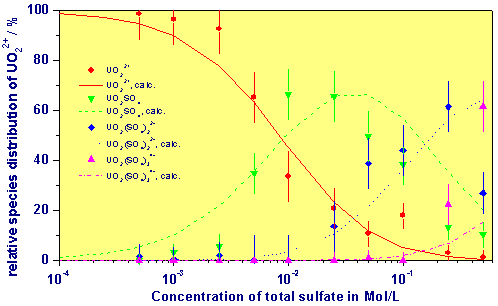
Comparison Between Measured and Calculated Species Distribution as Function of the Concentration of Sulfate at pH = 2 and I = 1 M
Ref.: G. Geipel, A. Brachmann, V. Brendler, G. Bernhard, and H. Nitsche. Uranium(VI) Sulfate Complexation studied by Time-Resolved Laser-Induced Fluorescence Spectroscopy (TRLFS). Radiochim. Acta 75, 199-204 (1996)
Time-Resolved Laser-Induced Fluorescence Spectroscopy with Ultrashort Laser pulses
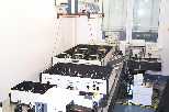 The described Time-Resolved Laser-Induced Fluorescence Spectroscopy allows measurements down to fluorescence lifetimes of a minimum of about 20 ns. This is caused by the duration of 10 ns of the Nd:YAG Laser pulse and the time resolution of the pulse generator for controlling of the used intensifier (5ns). In systems containing organic fluorescent components the fluorescence lifetime often is in the range below 10 ns. To study such components laser systems with much shorter pulse duration and also detection systems with a resolution below 1 ns have to be used. A system for TRLFS in this fluorescence lifetime range was built up at the Institute of Radiochemistry recently.
For the generation of ultrashort laser pulses (130 fs - 2 ps) a complex light amplifier system is used. A cw-Laser pumps a mode-locking oscillator system to generate a ultrashort laser pulse. The energy of this laser pulse is very low, only a few nJ. For excitation of the samples this energy is too low, therefore the laser pulse has to be amplified. Laser pulses of such a short pulse duration cannot be amplified directly. The figure shows in principle the used method of a regenerative amplifier.
First, the duration of the laser pulse will be prolonged (stretched, see the picture of the pulse stretcher/compressor). This laser pulse has now a duration of about 200 ps and it is possible to amplify this pulse in the regenerative amplifier. To do so, laser pulses of a Nd:YLF laser were used. The output energy of this regenerative amplifier (1.5 mJ) is enhanced in a second amplifier. Using this second step of amplification the energy of the pulse reaches about 4 mJ.
After the amplification the pulse duration has to be shortened to the original pulse duration of the input laser. This is done in the so called compressor. The next step in our system is the generation of a tunable laser pulse. We use for this an optical parametrical amplifier (OPA). This enables us to generate laser pulses in the wavelength range from 300 nm up to 10 µm. In addition to the excitation of samples at fixed wavelength, it is possible to generate the second and third harmonic (400 nm and 266 nm) of the output of the amplifier system (800 nm). Using these ps- or fs- laser pulses the sample can be excited and the fluorescence light, coming from the sample, is measured in its spectral distribution using an intensified CCD-camera coupled to a 275 mm spectrograph. This CCD camera is specially designed for measurements of fluorescence lifetime shorter than 20 ns.
The principal scheme is analogous to the normal Time-Resolved Laser-Induced Fluorescence Spectroscopy, but in this case a much more complex Femtosecond-laser system is used instead of the Nd:YAG laser. In connection with intensified CCD-camera we are able to measure fluorescence lifetimes in the range from 200 ps up to 20 ns. Also the repetition rate of this laser system is much higher (1 kHz) than with the Nd:YAG laser (10 Hz), therefore the measurement can be done faster.
Example:
The following figures show a time resolved fluorescence spectrum of a purified Aldrich humic acid.
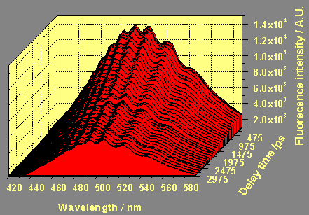
a) Time Resolved Fluorescence Spectrum of Purified Aldrich Humic Acid in the Delay Range from 0 to 3000 ps with a Step Width of 25 ps
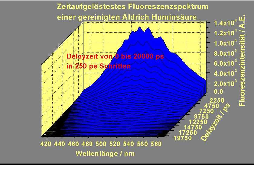
b) in the delay range from 0 to 20000 ps with a step with of 250 ps
From these two spectra the fluorescence decay curve (fluorescence lifetime) presented in the following figure results. 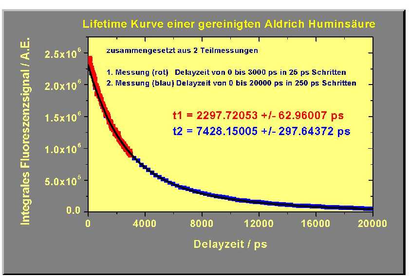
The two fluorescence lifetimes of the Aldrich humic acid were calculated using the connected decay curve to be: 2297 ± 62 ps and 7430 ± 300 ps.
Links:
Questions and remarks (E-Mail): G.Geipel@hzdr.de

