Conductivity Wire-Mesh Sensors
Objectives
Conductivity wire-mesh sensors have been developed for the investigation of fluid flows with and without gas fractions. The measurement principle is based on a local measurement of electrical conductivity of the fluid within the cross-section of a vessel or pipe by means of a mesh of crossing electrodes. The wire-mesh sensor can measure the conductivity distribution at high sampling rates and with a spatial resolution down to 2 mm. There are many application areas of these sensors. One main research field in our department today relates to basic experimental studies of gas/water and steam/water two-phase flows in safety relevant thermohydraulic components of nuclear power plants. Such studies are conducted for analysis of accident scenarios, and validation, as well as development of multi-phase thermohydraulic simulation codes such as CFX. As an example, wire-mesh sensors are a part of the instrumentation of departmental thermohydraulic test facilities, such as TOPFLOW, where wire-mesh sensors are used to obtain flow maps for vertical and horizontal pipeline flows. Through evaluation of velocity and gas fraction profiles, generalised models for the behaviour of two-phase flows under given geometric and thermodynamic boundary conditions are derived. Further current application areas for wire-mesh sensors are the investigation of substance mixing problems in chemical process plants and models of nuclear reactors, the investigation of cavitation and pressure shock phenomena in fluid pipelines, and water transport processes in soil.
Principle
|
The principle construction of a wire-mesh sensor for the examination of flows in a pipeline segment is shown in the right image. The sensor is essentially a mesh of wire or bar electrodes, one plane of electrodes being the current emitter electrodes and another plane arranged orthogonal to the emitter plane being the current receiver electrodes. Between the emitter and receiver electrodes, there is a gap of a few millimetres distance where conductivity is measured in the crossing points of the electrodes.
|
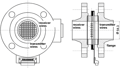 |
For that purpose, the control electronics switches the emitter electrodes consecutively onto a defined electrical potential relative to the environment (ground potential of fluid and pipe metal material) and the current that flows to the receiver electrodes is measured at each electrode in parallel. In order to eliminate DC offsets and to protect the sensor from electrochemical potentials, a bipolar emitter pulse scheme is used and then receiver electronics measures the difference signal at each bipolar pulse. The small receiver current is amplified and converted to a voltage by means of transimpedance amplifier circuits and eventually converted to a digital signal that is transferred to the measurement PC by means of a fast digital signal processing electronics. Special care has been given to low cable capacitances and low input and output impedances of the transmitter and receiver circuits in order to minimise electrode cross-talk at high measurement frequencies. The dynamic range of the conductivity measurement is between 0.1 µS/cm (destilled water) and 1,000 µS/cm (tap water). In case of gas/water or oil/water two-phase mixtures, the comparatively high conductivity difference of the two phases can be measured directly with the sensor. For single-phase flows, it is possible to use conductivity tracers, such as NaCl to label partial fluid volumes.
Sensor Types
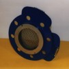
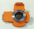
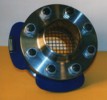
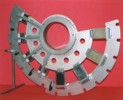
Conductivity wire-mesh sensors can be manufactured with different measuring cross-sections and operational parameters, depending on the particular application. The typical operating range of the sensors is at temperatures up to 100 °C (150 °C for shorter time intervals) and at maximum pressure of 7 MPa (70 bar). The latest sensors achieve a maximum time resolution of 10,000 frames per second and can be used in pipeline cross-sections of up to 200 mm diameter, at mixture velocities of up to 10 m/s and with 64 x 64 electrodes. The spatial resolution in the measurement plane (electrode spacing) can be made as small as 2 mm. In the future, the development of sensors for high temperatures of up to 300 °C is planned.
Photo Galery
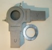
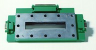
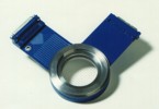
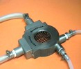
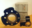
(Please click on the sensor photo and you will find more details on the corresponding sensor type.)
 |
 |
 |
|
 |
 |
 |
|
 |
 |
 |
|
 |
 |
 |
 |
Data Processing
|
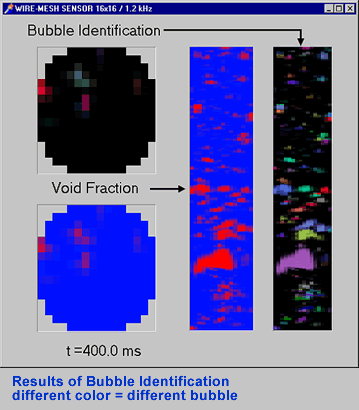
The data of a wire-mesh sensor consists of a time sequence of digitally coded conductivity values for each mesh point. The first step of data processing is the determination of absolute conductivity values or alternatively an assignment of the relative conductivity values to the corresponding phases that are presented in the flow. As a result, we obtain the conductivity or phase distribution within the measurement plane at a contiguous sequence of temporal sampling points - thus a three-dimensional data volume. From data of gas/water two-phase flows, it is possible to compute axial and radial gas fraction profiles and the integral gas fraction by proper integration of the gas fraction over certain cross-section areas. For the determination of gas bubble size distributions from raw data, special data analysis algorithms were developed that can identify single bubbles by means of a filling algorithm, and compute volume, as well as equivalent bubble diameters accordingly. Furthermore, it is possible to measure the velocity distribution of the gas phase by placement of two wire-mesh sensors with a small axial spacing in the flow. Since the conductivity distribution reaches the second sensor with only minor spatial structure modifications with a time shift that is determined by the flow velocity after having passed the first sensor, we can obtain the local velocity values within the measurement cross-section from a computational cross-correlation analysis of the two sensor signal.
|
 |
Publications
- Prasser, H.-M.; Böttger, A.; Zschau, J.
A New Electrode-Mesh Tomograph for Gas-Liquid Flows
Flow Measurement and Instrumentation 9 (1998) 111-119. - Prasser, H.-M.; Scholz, D.; Zippe, C.
Bubble size measurement using wire-mesh sensors
Flow Measurement and Instrumentation 12/4 (2001) 299-312. - Prasser, H.-M.; Krepper, E.; Lucas, D.
Evolution of the Two-Phase Flow in a Vertical Tube - Decomposition of Gas Fraction Profiles according to Bubble Size Classes using Wire-Mesh Sensor
International Journal of Thermal Sciences 41 (2002) pp. 17-28. - Lucas, D.; Krepper, E.; Prasser, H.-M.
Experimental investigation and modeling of air/water flows in vertical pipes
Heat and Mass Transfer, Springer-Verlag (eingereicht) - Höhne, T.; Grunwald, G.; Prasser, H.-M.
Experimental Investigations on the Four-Loop Test Facility ROCOM
Kerntechnik 65/5-6, S. 212-215. - Prasser, H.-M.; Böttger, A.; Zschau, J.
Hochauflösende Gittersensoren für Gas-Flüssig-Strömungen
MSR Magazin (1998)H. 1-2, S. 12-15. - Misawa, M.; Tiseanu, I.; Prasser, H.-M.; Ichikawa, N.; Akai, M.
Ultra-fast x-ray tomography for multi-phase flow interface dynamic studies
Kerntechnik 68 (2003) 3, pp. 85-90. - Grunwald, G.; Höhne, T.; Kliem, S.; Prasser, H.-M.; Richter, K.-H.; Rohde, U.; Weiß, F.-P.
Versuchsanlage ROCOM zur Untersuchung der Kühlmittelvermischung in Druckwasserreaktoren - Ergebnisse quasistationärer Vermischungsexperimente
Wissenschaftlich-Technische Berichte / Forschungszentrum Rossendorf; FZR-348 Juli 2002.


