Positron annihilation spectroscopy (PAS)
Positron annihilation spectroscopy (PAS)
Head:
Dr. sc.nat. Gerhard Brauer
-
Co-worker:
Dipl.-Phys. Wolfgang Anwand
Goal:
- Investigation of vacancy-type defects in solids and surfaces
Research topics:
- investigations of vacancy-type defects caused by ion implantation
- investigations of precipitates.
- investigations of radiation-induced damage.
- investigations of thin films and interfaces.
- methodical developments.
Results
- Ionic crystals / Polymers / Glasses
- Metals / alloys
- Theory / Methodology / Review
- Flash lamp annealing
- ZnO
- EPOS-project at ELBE
- Hydrogen-defect interaction
- SiC
- SiO2 / Si
- Zirconia
Equipment:
-
conventional positron lifetime and Doppler broadening spectroscopy
system 1 :combined conventional positron lifetime and Doppler broadening measuring system,sample temperatures ranging from 10 K to room temperature.system 2 :single lifetime system, sample at room temperature.
-
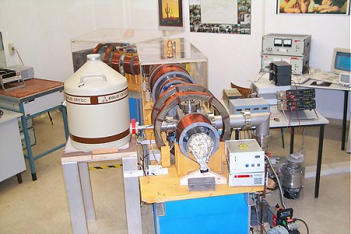
mono-energetic positron beam for Slow Positron Implantation Spectroscopy (SPIS)
magnetically guided mono-energetic positron beam,beam spot diameter 4 mm, high vacuum conditions,
accelerator voltage from 30 V to 36 kV, measurement of the Doppler broadening of the positron
annihilation line in dependence on the incident positron energy using a Ge detector,
resolution of the Ge detector (1.09 + 0.01) keV at 511 keV.
|
|
|
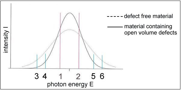
MethodSlow Positron Implantation Spectroscopy (SPIS): Positrons of predetermined energies E (30 eV – 36 keV) are implanted at depths of up to a few micrometer in the sample. The motion of positron-electron pairs prior to annihilation causes a Doppler broadening of the photopeak in the measured energy spectrum of the annihilation photons characterized by the lineshape parameter S. S is higher for positrons trapped at and annihilated in open-volume defects. |
Sketch of the annihilation line changes
 |
|
 |
Experimental setup
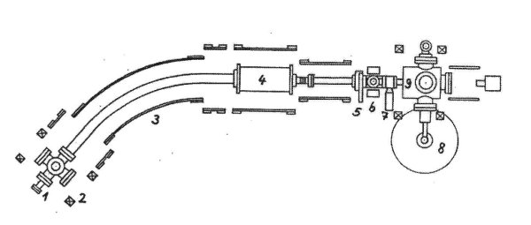 |
| 1 positron source 2 Helmholtz coils 3 solenoids 4 accelerator 5 iris aperture 6 beam movement coils 7 valve 8 Ge-detector 9 sample chamber |
Data
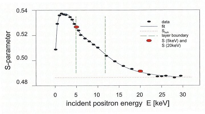
The figure shows an S parameter vs. positron energy E plot of a 6H-SiC sample implanted with Ge+ ions. Based on the S(E)-data, a numerical solution of the positron diffusion equation is possible using the software package VEPFIT [1]. Thereby a Makhovian profile for the distribution of the thermalized positrons in the sample is assumed.
 |
Evaluation
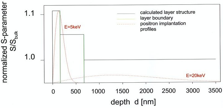 |
The fit is based on the assumption of a certain number of box-shaped depth profiles of vacancy-type defects created by the Ge+ implantation. The width of a box represents the depth and the height of a box is connected with size and concentration of a given defect.
[1] A.van Veen et al., in Positron Beams for Solids and Surfaces, edited by P.J.Schulz et al.,
AIP Conf. Proc. No. 218 (AIP New York 1990), p. 171
