Elektronenstrahlparameter des ELBE-Strahls
1. Strahlparameter des ELBE-Beschleunigers
2001 war ein entscheidendes Jahr für die Strahlungsquelle ELBE. Alle Komponenten der ersten Ausbaustufe von ELBE wurden erfolgreich in Betrieb genommen. Die wesentlichen Strahleigenschaften wurden bestimmt und es konnte gezeigt werden, daß alle wichtigen Vorgabegrößen des ELBE-Beschleunigers erreicht wurden. Alle Messungen befinden sich in guter Übereinstimmung mit früheren Simulationen. Auf Grund von Verunreinigungen der supraleitenden Kavitäten ist der erreichte Beschleunigungsgradient, speziell in der zweiten Kavität, geringer als vorausberechnet. Darum wurden Strahlparameter wie Bunchlänge und Emittanz bei einer Energie von 12 MeV anstatt bei den vorher erreichten 20 MeV gemessen.
Die folgende Tabelle zeigt die wichtigsten 2001 gemessenen Strahlparameter.
| Maximale Strahlenergie |
20 MeV |
| Maximale Bunchladung |
77 pC |
| Maximaler Strahlstrom |
0.85 mA bei 12 MeV |
|
| |
bei 1 pC
Bunchladung |
bei 77 pC
Bunchladung
(zusammen) |
bei 77 pC
Bunchladung
(einzeln) |
Energiebreite
Transversale Emittanz
Bunchlänge |
35 keV
3 p mm mrad
- |
55 keV
10 p mm mrad
2.5 ps |
40 keV
8 p mm mrad
2.0 ps |
|
2. Bunchlängenmessungen
Die Elektronen-Bunchlänge an ELBE liegt im Bereich von Pikosekunden und korrespondiert somit mit einer Bandbreite im THz-Bereich. Die direkte elektrische Messung ist aufgrund der zu geringen Kabel- und Wellenleiter-Bandbreiten nicht möglich. Während der Inbetriebnahme des ersten ELBE-Beschleunigermoduls wurde die Bunchlänge mittels optischer Übergangsstrahlung (OTR) gemessen. Die wichtigsten Merkmale dieser Technik werden im folgenden kurz beschrieben.
Die Übergangsstrahlung entsteht wenn Elektronen die Grenzfläche zwischen zwei Medien mit unterschiedlicher Dielektrizitätskonstante passieren. Die Zeitverzögerung der Übergangsstrahlung ist gleich Null. Auf Grund dessen ist die longitudinale Form des Strahlungspulses eine Kopie der Form des Elektronenbunches. Bei den Messungen wurde ein Martin-Puplett-Interferometer (MPI) [1] verwendet um die Autokorrelationsfunktion der OTR-Impulse (siehe Bild 1) zu bestimmen. Daraus läßt sich das Leistungsspektrum des Elektronenstrahls berechnen und mit dem Spektrum des Strahls mit erwarteter Form und Größe vergleichen.
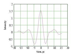 |
Bild 1: Interferogramm obtained by scanning the time delay between the two optical paths of the interferometer. |
A 10 µm thick aluminum foil streched over a frame was used to produce the CTR. The view screen is oriented 45° to the beam direction. Thus the backward CTR is propagating perpendicular to the electron beam. We have used crystal-quartz window for the output of the CTR from the beam line. An interferometric technique was already successfully used at TTF for the electron bunch length measurements [2]. We have modified the interferometer with the goal to use Golay cell detectors instead of pyro detectors, which are used in the original design. A video camera was also installed at the interferometer so that we could see the size and the position of the electron beam on the view screen.
Bunch length behavior was studied at different bunch charges as a function of RF field phase in the first accelerating cavity. The first cavity determines the bunch length since the electrons become relativistic there and then bunch length remains constant. The bunch length was measured to be minimum 2 ps RMS at 77 pC bunch charge. Fig. 2 shows the results of the measurements. The results are in good agreement with PARMELA simulations.
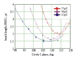 |
Fig. 2: Bunch length vs. phase of the first cavity. |
3. Emittance Measurements
For many applications of the ELBE electron beam the transverse emittance is a crucial parameter. For radiation physics experiments a very low transverse emittance is required to allow as many electrons as possible to become trapped into channeling states when entering a crystal. The operation of free-electron lasers puts some requirements on the transverse emittance as well in order to acchieve a good overlap between the electron beam and the optical mode over the whole length of the undulator.
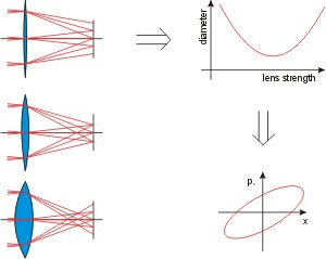
| Therefore, the transverse emittance of the ELBE electron beam was measured for typical bunch charges and for varying settings of the main accelerator controls. All measurements were done at 12 MeV beam energy using the quadrupole-scan method which is illustrated here. Basically, this method applies a variable lens (in this case a magnetic quadrupole) and detects the focal spot diameter on a viewscreen. From the dependence of the focal spot diameters on the strength of the lens the complete first-order parameter-set describing the transverse phase-space of the beam can be derived. So, Fig. not only shows the measured emittance for varying RF-phase of the first accelerator cavity but also displays the estimated phase space ellipses to show correlations within the beam. |
 |
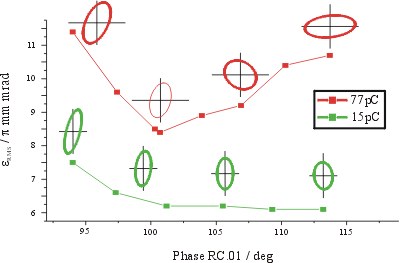 |
Fig. 3: Normalized transverse emittance of the ELBE electron beam for two different bunch charges measured with the quadrupole scan method at 12 MeV beam energy for varying RF-phases of the first accelerator cavity. |
Such emittance measurements have been done for several bunch charges ranging from 1 pC to the FEL-mode at 77 pC. In all cases the measured values agree well to those previously measured at the ELBE injector using a pepper-pot mask. This indicates that the emittance growth during the beam capture into the RF-field of the first cells of the cavity is negligible. A normalized emittance of less than 3 p mm mrad was measured at 1 pC bunch charge which could be cut down even further for radiation physics experiments using apertures in the injector. At full bunch charge the best measured values were below 8 p mm mrad. However, for FEL operation the accelerator controls have to be set to meet some compromize between best transverse emittance and the requirements of a low energy spread and a short bunch length. In this case 10 p mm mrad can be reached.
[1] P. Michel, P. Piot: FZD Annual Report 1999 Institut of Nuclear and Hadron Physic, 9
[2] M. Geitz et al., Proceedings of the 1999 Particle Accelerator Conference, New York, 1999, 2172-2174

