Electron Beam Diagnostics at ELBE
Accurate beam instrumentation and diagnostics is essential for smooth commissioning of the accelerator. The diagnostics for ELBE has two main purposes: (i) to allow the set-up of the accelerator and (ii) to monitor the beam properties during the runs. The setup of the accelerator will be performed in a low beam-power mode with reduced micropulse repitition rates. This is essential in order to limit the possible beam loss and activation of accelerator components. For this reason, the set-up diagnostics should be sensitive to low average beam currents. On the other hand, the monitor diagnostics should be robust enough to resist the high power electron beam. The following table shows the electron-beam parameters to be measured together with the corresponding instrumentation for set-up and the monitoring parameters, respectively.
| set up parameter | detector |
| beam location/profile | OTR viewer / fluorescent viewer |
| transverse emittance | quadrupole & viewer / multislit masc & viewer |
| low beam current | Faraday cup |
| energy spread | dipole & OTR viewer |
| bunch length | OTR & Martin Puplett interferometer |
| monitor parameter | detector |
| beam location | strip-line monitor |
| high beam current | RF monitor / beam dump & Faraday cup |
| beam loss | photomultiplier tubes |
OTR viewer
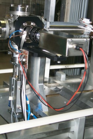 |
Insertable optical transition radiation (OTR) viewers will be used to observe electron beam profile and position throughout the machine. Backward scattered OTR is produced on 6 mm Al foils. The radiation will be detected by commercial Vidicon cameras Heimann KH 500 with XQ 1300 SF Vidicon tubes. Spatial resolution below 100 mm and linear response on the current density are the main advantages of this methode. We use the insertable OTR-viewer module. Because of the low OTR efficiency in the injector energy region of 250 keV, fluorescent viewers (Cr-doped Al2O3 ceramics) are applied. |
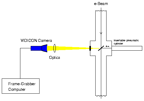
Measurement of transverse emittance
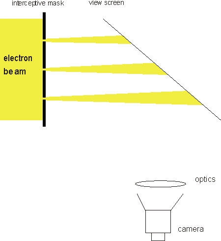
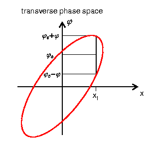
At 250 keV, we measure the transverse emittance of the bunched beam (space-charge dominated beam) by means of the multislit-mask technique
Basic idea:
|
- The beam-spot size is sampled by an interceptive |
 |
|
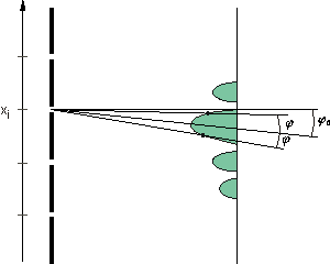
- The generated beamlets propagate in a drift space to allow the transverse divergence (angle j, lower picture) to impart a significant contribution to the beam size. |
 |
- The emittance is then computed (twiss parameters). |
 |
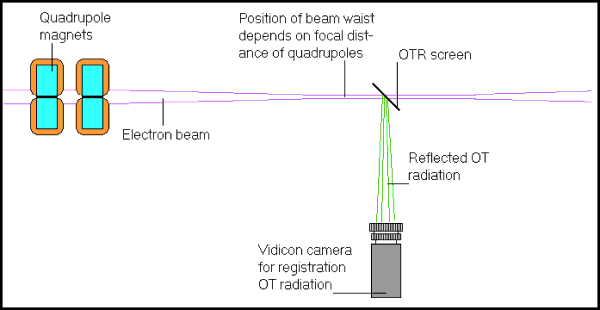
At 40 MeV, the transverse emittance will be measured with the so called Quadrupole Scan Methode
Basic idea:
|
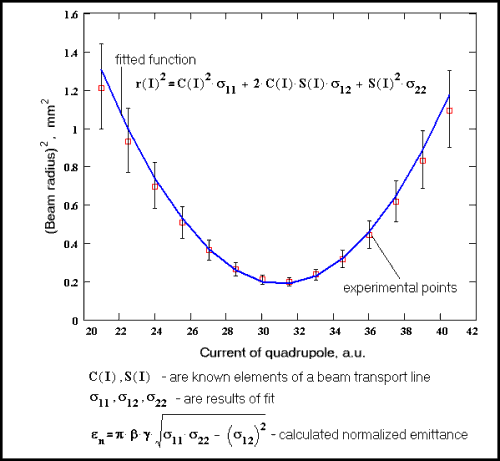
- The field strength of a quadrupole (solenoid) is varied such that the beam size on the screen located behind the quadrupole goes through a minimum. |
 |
|
- The rms beam radius and the corresponding quadrupole current is measured and |
 |
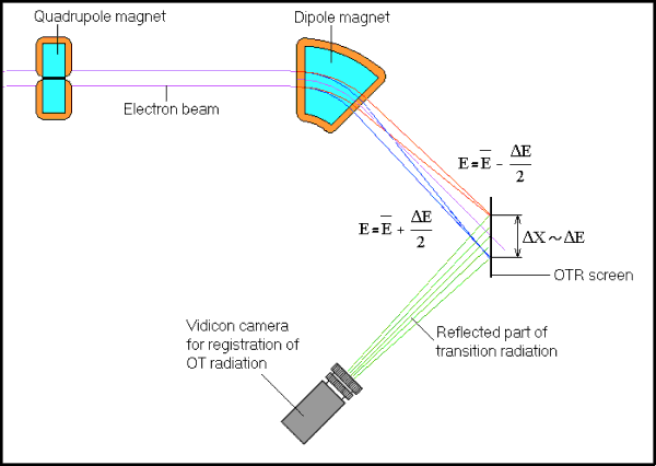
Measurement of energy spread
Basic idea:
|
- The beam size in dispersive regions (e.g. behind the dipole in the dipole bending plane) is measured by means of a beam viewer. |
 |

